THEFT DETERRENT SYSTEM Certification ECU Power Source Circuit
DESCRIPTION
This circuit provides power to operate the certification ECU.
WIRING DIAGRAM
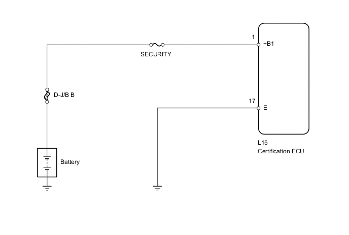
PROCEDURE
-
INSPECT FUSE (SECURITY)
-
Remove the SECURITY fuse from the main body ECU.
-
Measure the resistance of the fuse.
Standard resistance Tester Connection Condition Specified Condition SECURITY fuse Always Below 1 Ω
NG 
REPLACE FUSE
OK 
-
-
CHECK HARNESS AND CONNECTOR (CERTIFICATION ECU - BATTERY AND BODY GROUND)
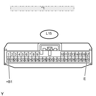
*1 Front view of wire harness connector: (to Certification ECU)
-
Disconnect the L15 ECU connector.
-
Measure the resistance and voltage according to the value(s) in the table below.
Standard resistance Tester Connection Condition Specified Condition L15-17 (E) - Body ground Always Below 1 Ω Standard voltage Tester Connection Condition Specified Condition L15-1 (+B1) - Body ground Always 11 to 14 V
OK
PROCEED TO NEXT CIRCUIT INSPECTION SHOWN IN PROBLEM SYMPTOMS TABLE Click here
NG
REPAIR OR REPLACE HARNESS OR CONNECTOR
-