THEFT DETERRENT SYSTEM, Diagnostic DTC:B276A
| DTC Code | DTC Name |
|---|---|
| B276A | Short to GND in Tilt Sensor Signal Circuit |
DESCRIPTION
-
This DTC is stored when terminal CSIF of the tilt sensor (yaw rate sensor) has not received a signal for 5 seconds or more.
| DTC Code | DTC Detection Condition | Trouble Area |
|---|---|---|
| B276A | Terminal CSIF of tilt sensor (yaw rate sensor) has not received signal for 5 seconds or more |
|
WIRING DIAGRAM
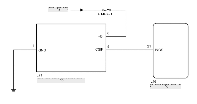
| *a | from Battery |
| *b | Tilt Sensor (Yaw Rate Sensor) |
| *c | Certification ECU |
CAUTION / NOTICE / HINT
Note
-
If the certification ECU is replaced, refer to the Service Bulletin.
-
When replacing the tilt sensor (yaw rate sensor), perform zero point calibration Click here.
-
Inspect the fuses for circuits related to this system before performing the following inspection procedure.
PROCEDURE
-
CHECK TILT SENSOR (YAW RATE SENSOR) (CSIF)
-
Using an oscilloscope, check the waveform.
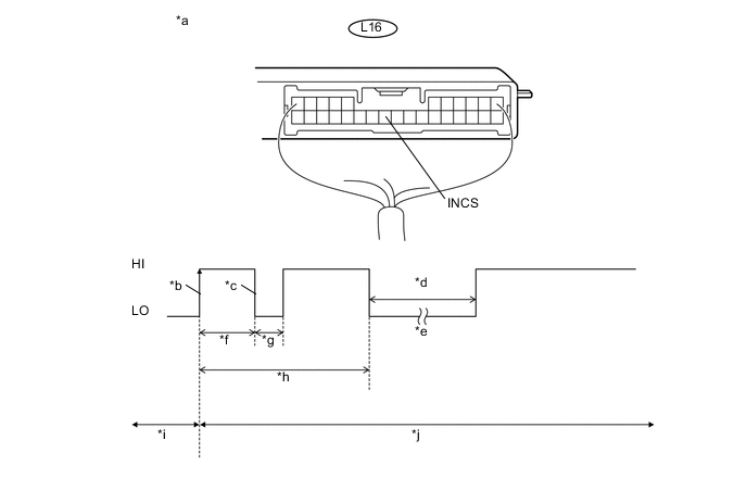
Text in Illustration *a Component with harness connected
(Certification ECU)
*b CSIF Initial Signal *c CSIF Initial Response *d Approximately 1.0 seconds *e Initial Diagnosis *f Approximately 1.0 to 1.6 seconds *g Approximately 0.05 seconds *h Approximately 5.5 seconds *i Disarmed State *j Arming Preparation State Measurement Condition Tester Connection Content Tester Connection L16-21 (INCS) - Body ground Tool Setting 2 V/DIV., 100 ms./DIV. Condition Theft deterrent system is set (system changes from disarmed state to arming preparation state) Tech Tips
-
If the tilt sensor (yaw rate sensor) is normal, an initial response is output in response to the HI input from the certification ECU.
-
If the waveform output remains LO, there may be a problem with the certification ECU, as there is no input from the certification ECU.
OK The waveform displays properly (HI is 6.5 V or higher and LO is below 1 V). -
OK 
USE SIMULATION METHOD TO CHECK Click here
NG 
-
-
CHECK TILT SENSOR (YAW RATE SENSOR) (CSIF)
-
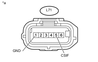
Text in Illustration *a Front view of wire harness connector
(to Tilt Sensor [Yaw Rate Sensor])
Disconnect the tilt sensor (yaw rate sensor) connector.
-
Measure the voltage according to the value(s) in the table below.
Standard Voltage Tester Connection Condition L71-5 (CSIF) - L71-1 (GND) Immediately after theft deterrent system set Result Result Proceed to CSIF voltage is below 1 V when theft deterrent system is set A CSIF voltage is 6.5 V or higher when theft deterrent system is set B Tech Tips
With connector L71 of the tilt sensor (yaw rate sensor) disconnected, measure the voltage at CSIF when the theft deterrent system is set.
B
REPLACE TILT SENSOR (YAW RATE SENSOR) Click here
A
-
-
CHECK HARNESS AND CONNECTOR (CERTIFICATION ECU - TILT SENSOR [YAW RATE SENSOR])
-
Disconnect the L16 certification ECU connector.
-
Disconnect the L71 tilt sensor (yaw rate sensor) connector.
-
Measure the resistance according to the value(s) in the table below.
Standard Resistance Tester Connection Condition Specified Condition L16-21 (INCS) - L71-5 (CSIF) Always Below 1 Ω L16-21 (INCS) - Body ground Always 10 kΩ or higher
OK
REPLACE CERTIFICATION ECU
NG
REPAIR OR REPLACE HARNESS OR CONNECTOR
-