AIR CONDITIONING SYSTEM SYSTEM DESCRIPTION
-
GENERAL
-
The air conditioning system has the following features:
-
The optional multi-zone automatic climate control system (controlled by the neural network) is available on this vehicle. When the 4-ZONE switch is ON, the temperature, airflow mode and airflow volume of each of the 4 seats (driver, front passenger, rear left, rear right) is automatically adjusted.
-
As a standard, the front seat independent temperature climate control system (controlled by the neural network) is in this vehicle. A non-sliding type film damper is used to provide independent airflow volume for the right and left side of the vehicle.
-
The multi-zone automatic climate control system has a 4-ZONE switch, and the front seat independent temperature climate control system has a DUAL switch.
-
The registers on the center pillars help improve airflow to the rear seats.
-
For vehicles with the rear cooler, there are roof and roof side air ducts, and independent temperature and airflow mode adjustments are automatically performed.
-
The rear cooler unit has a rear seat independent temperature climate control system, an odor filter for the air purification function, and a cool box.
-
For the long body VIP specification, an infrared ray sensor unit is installed. The infrared ray sensor unit detects the body temperature of the rear seat passenger, compares the body temperature to a specified setting, and attempts to decrease the temperature difference.
-
The Positive Temperature Coefficient (PTC) heater system contains a PTC heater that heats the air that has passed through the heater core to ensure the proper heater performance.
-
A compact, lightweight, and highly efficient straight flow (full-path flow) aluminum heater core is used.
-
The pollen removal mode control is used to remove pollen in the area around the upper areas of the driver and front passenger seats.
-
The air conditioning amplifier is equipped with a self diagnosis function. If there is a malfunction in the system, it stores the DTCs (Diagnostic Trouble Codes) in its memory.
-
-
-
MODE POSITION AND DAMPER OPERATION
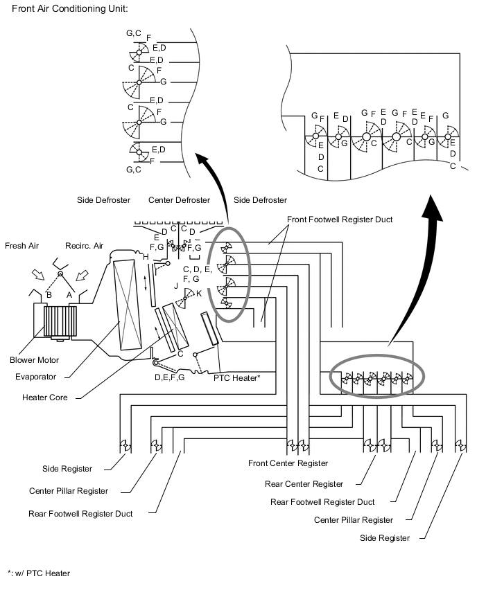
Control Damper Control Position Damper Position Operation Air Inlet Control Damper FRESH A Brings in fresh air. RECIRC B Recirculates internal air. Air Mix Control Film Damper MAX COOL to MAX HOT J, K Varies mixture ratio of fresh air and recirculation air in order to regulate temperature continuously from HOT to COOL. Cool Air Bypass Control Damper MAX COOL to MAX HOT H, I Cool air blows out of front center register and side registers, in order to adjust temperature around head of occupants during cooling or warming. Mode Control Damper 
FACE
G Air blows out of front and rear center registers, center pillar register, and side register. 
BI - LEVEL
F Air blows out of front and rear center registers, side register, center pillar register and front and rear footwell register ducts. 
FOOT
E Air blows out of front and rear footwell register ducts, and side register..
In addition, air blows out slightly from center and side defrosters.

FOOT / DEF
D Air blows out of center defroster, side defroster, side register, and rear center register to defrost windshield.
Air also blows out from front and rear footwell register ducts.

DEF
C Air blows out of center and side defrosters and side registers to defrost windshield. 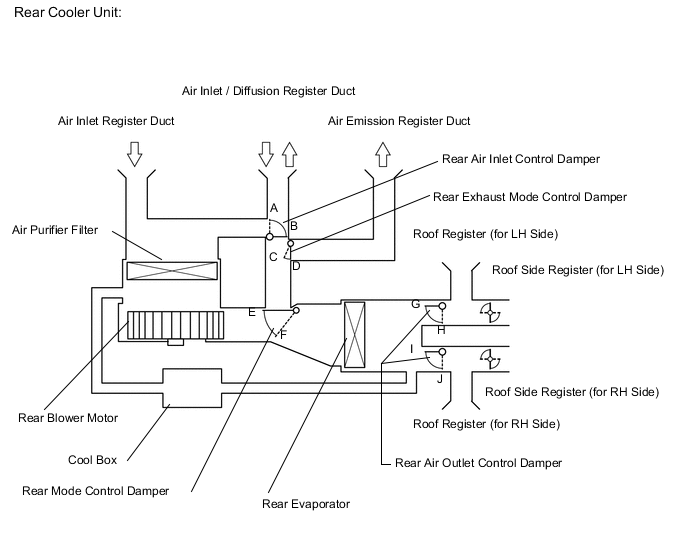
Control Damper Control Position Damper Position Operation Air Inlet / Outlet Control Damper & Exhaust Control Damper Air Purifier ON
(FRESH Mode)
A, C, F, H, J Cleaned air is discharged from air vent in luggage compartment. Air Purifier ON
(RECIRC Mode)
A, D, F, H, J Cleaned air blows out of diffusion register duct. Rear Cooler ON B, E, G, I Air blows out of roof side register and roof register. -
AIR OUTLETS AND AIRFLOW VOLUME
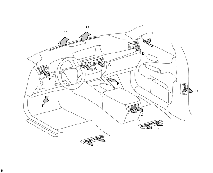
Air Outlet Mode Selectable Mode Register Footwell Defroster Front Face Rear Face Automatic Manual Center Side Center Side Front Rear Center Side Air Outlet Position Symbol A B C D E F G H FACE U 


FACE L 
B/L U 
B/L L FOOT D FOOT R FOOT F F/D DEF Tech Tips
-
The size of the circle indicates the proportion of airflow volume.
-
FACE U: Air flows from registers only
-
FACE L: Air flows from registers and footwells
-
B/L U: Standard B/L mode
-
B/L L: B/L mode in which large amount of air flows from footwells
-
FOOT D: FOOT mode in which large amount of air flows from defroster
-
FOOT R: FOOT mode in which large amount of air flows from rear footwells
-
FOOT F: Standard FOOT mode
-
F/D: Standard FOOT / DEF mode
-
DEF: Standard DEF mode
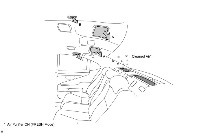
Air Outlet Mode Selectable Mode Register Automatic Manual Roof Roof Side Air Outlet Position Symbol A B 
FACE Tech Tips
The size of the circle indicates the proportion of airflow volume.
-