ELECTRIC POWER CONTROL SYSTEM TERMINALS OF ECU
-
CHECK ELECTRIC POWER CONTROL ECU (PASSENGER SIDE JUNCTION BLOCK)
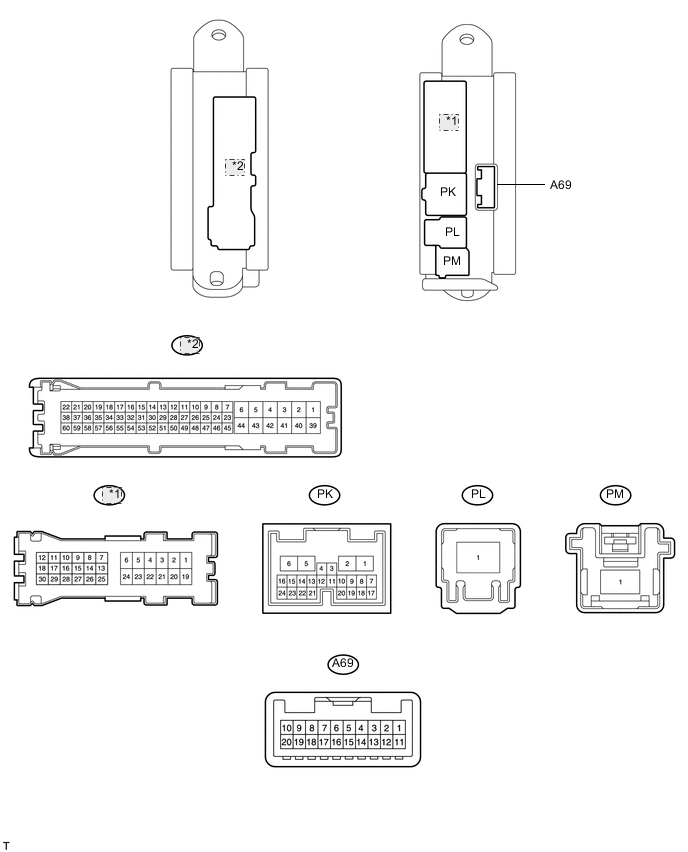
*1 PJ *2 PA
-
Disconnect the PA, PM, PK and A69 ECU connectors.
-
Measure the resistance and voltage according to the value(s) in the table below.
Terminal No. (Symbols) Wiring Color Terminal Description Condition Specified Condition PA-39 (GND) - Body ground W-B - Body ground Ground Always Below 1 Ω A69-8 (VB-) - Body ground W-B - Body ground Voltage detection (-) Always Below 1 Ω PM-1 (BECU) - Body ground L - Body ground ECU power supply Always 11 to 14 V PM-1 (BCUT) - Body ground L - Body ground Power cut linked power (input) Always 11 to 14 V A69-18 (VB+) - Body ground BE - Body ground Voltage detection (+) Always 11 to 14 V PK-1 (IG) - Body ground G - Body ground IG power supply Engine switch on (IG) 11 to 14 V
-
If the result is not as specified, there may be a malfunction on the wire harness side.
-
-
Reconnect the PA, PM, PK and A69 ECU connectors.
-
Measure the voltage and resistance according to the value(s) in the table below.
Terminal No. (Symbols) Wiring Color Terminal Description Condition Specified Condition A69-12 (STSW) - PA-39 (GND) B - W-B Starter switch signal Engine switch on (IG) → Engine cranking Below 1 V → 8 to 14 V A69-6 (VC) - PA-39 (GND) B - W-B Sensor power supply Engine switch on (IG) 4.5 to 5.5 V A69-9 (IB) - PA-39 (GND) L - W-B Battery current detection Engine switch on (IG) 0.5 to 4.5 V A69-10 (E2) - PA-39 (GND) W - W-B Sensor ground Engine switch on (IG) Below 1 Ω A69-20 (THB) - PA-39 (GND) P - W-B Battery temperature detection Engine switch on (IG) 0.5 to 4.5 V PA-57 (CUTD) - PA-39 (GND)
PA-35 (CUTD) - PA-39 (GND)
B - W-B
B - W-B
Power cut linked power (output) Engine switch on (IG) 11 to 14 V
-
If the result is not as specified, the ECU may have a malfunction.
-
-