NIGHT VIEW CAMERA ADJUSTMENT

CAUTION / NOTICE / HINT
Tech Tips
Perform the night view camera adjustment if any of the following occurs: 1) the No. 1 night view ECU is replaced, 2) the object recognition camera (with night view camera) is replaced, or 3) the toe-in is adjusted.
PROCEDURE
-
PREPARATION FOR ADJUSTMENT
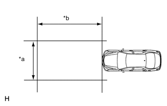
Text in Illustration *a 3 m (9.84 ft.) or more *b 4 m (13.1 ft.) or more
-
Prepare for adjustment.
-
Move the vehicle to a level surface.
Note
-
Make sure there is at least 4 m (13.1 ft.) with no obstacles in front of the vehicle, the area is level and there is no wind.
-
To the extent that it is possible, use an area where the wall in front of the vehicle has no patterns.
-
Make sure there are no black and white patterned objects in front of the vehicle.
-
Make sure that no objects come between the target and vehicle (camera) during adjustment.
-
Check that there are no reflective materials in the surroundings or on the ground within a 4 m (13.1 ft.) or more x 3 m (9.84 ft.) or more area in front of the vehicle.
-
Make sure the vehicle is in a place where the ambient brightness does not change.
-
-
Adjust the tire pressures to the specified pressure Click here.
-
Set the height control switch to normal.
-
Make sure the engine oil amount is correct.
-
Make sure the coolant amount is correct.
-
Make sure the spare tire is in its proper position. (w/ Spare Tire)
-
Make sure the standard tools are in their proper position.
-
Make sure there is no on board luggage.
-
Clean the front windshield glass.
-
If the lens of the night view camera is dirty, apply a small amount of lens cleaner to a clean, soft cloth and clean the lens.
-
-
Perform height control sensor adjustment Click here.
Note
Perform this procedure as accurately as possible.
-
Adjust the front wheel alignment.
-
for 2WD:
Adjust the front wheel alignment adjustment Click here.
Note
Perform this procedure as accurately as possible.
-
for AWD:
Adjust the front wheel alignment adjustment Click here.
Note
Perform this procedure as accurately as possible.
-
-
Adjust the rear wheel alignment Click here.
Note
Perform this procedure as accurately as possible.
-
Create the target sheet.
-
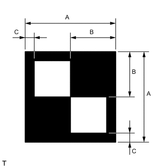
Print or copy the illustration. Check that the dimensions are +/- 5 mm (0.197 in.) of the ones in the table below.
Dimension Area Specification A 160 mm (6.30 in.) B 80 mm (3.15 in.) C 16 mm (0.630 in.) Note
-
Make sure that the black areas of the target sheets are not glossy.
-
Give priority to the height of the white inner target area when adjusting the size.
If the print or copy's dimensions are not as specified, adjust settings and reprint or recopy so that the print or copy's dimensions are as specified.

-
-
-
Determine the target placement point (original method).
Note
-
Perform this procedure as accurately as possible.
-
Do not place reflective materials in the area behind the target.
-
Make sure there are no patterns on the wall behind the target.
-
Make sure the distance between the target and wall is within 3 meters.
-
Make sure the target's shadow is not on the wall, as the system may mistakenly recognize it.
-
Do not place black and white patterned objects near the target.
-
Face the vehicle toward a wall with no patterns, etc. to make sure the background behind the target has no patterns.
-
Make sure SST (laser radar adjusting reflector) is positioned correctly.
-
From the center of the front bumper (center of the emblem), hang a weight with a pointed tip, and mark point B on the ground.
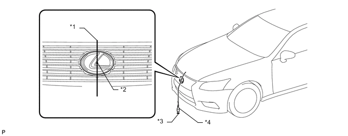
*1 String *2 Center *3 Point B *4 Weight -
From the center of the rear bumper (center of the emblem), hang a weight with a pointed tip, and mark point A on the ground.
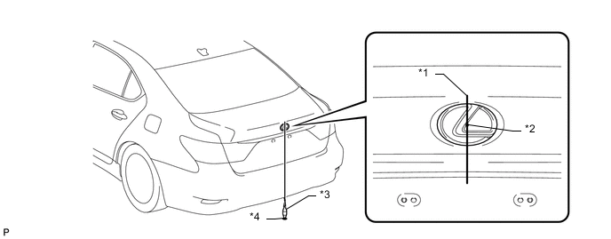
*1 String *2 Center *3 Weight *4 Point A -
Using a piece of string that uses point A as a starting point and that passes through point B, make a straight line on the ground ahead of the vehicle 3.5 m (11.5 ft.) or more from point B.
Tech Tips
-
Make sure to secure the string (using tape, etc.) when it is taut.
-
Lightly flick the string with your fingers several times to confirm that the string is aligned above point B.
-
-
Mark point C 955 mm (3.13 ft.) from the front bumper center point B (placement point 1).
-
Mark the placement point 218 mm (8.58 in.) from the point C.
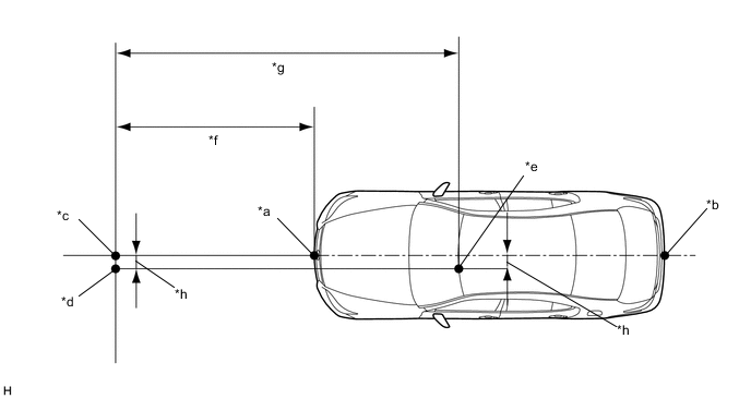
Text in Illustration *a Point B *b Point A *c Point C *d Target Placement Point *e Night View Camera Location *f 955 mm (3.13 ft.) *g 3020 mm (9.91 ft.) h 218 mm (8.58 in.)
-
-
Determine the target placement point (simple method).
Note
-
Perform this procedure as accurately as possible.
-
Do not place reflective materials in the area behind the target.
-
Make sure there are no patterns on the wall behind the target.
-
Make sure the distance between the target and wall is within 3 meters.
-
Make sure the target's shadow is not on the wall, as the system may mistakenly recognize it.
-
Do not place black and white patterned objects near the target.
-
Face the vehicle toward a wall with no patterns, etc. to make sure the background behind the target has no patterns.
-
Make sure SST (laser radar adjusting reflector) is positioned correctly.
-
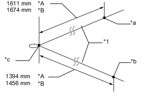
Text in Illustration *A HID Type Headlights *B LED Type Headlights *1 String *a Point R *b Point L *c Point T Prepare an 8 m (26.2 ft.) long string made out of a material that does not stretch easily, such as fishing line or some other type of nylon string. Make a knot in the center of the string (point T), and then while pulling the ends of the string, mark points L and R for the left and right sides respectively.
Standard HID Type Headlights From point T to point R: 1611 mm (3.81 ft.) From point T to point L: 1394 mm (4.57 ft.) LED Type Headlights From point T to point R: 1674 mm (5.49 ft.) From point T to point L: 1456 mm (4.48 ft.) -
Securely attach points R and L to the center marks of the low beam headlight bulbs on the headlights.
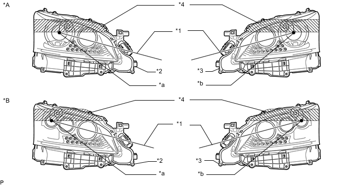
Text in Illustration *A HID Type Headlights *B LED Type Headlights *1 String *2 Right Side Headlight *3 Left Side Headlight *4 Protective Tape *a Point R *b Point L -
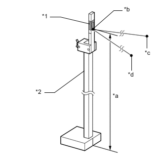
Text in Illustration *1 Protective Tape *2 SST (Laser Radar Adjusting Reflector) *a Point R *b Point L *c Point T *d 1305 mm (4.28 ft.) Securely attach point T to SST (laser radar adjusting reflector) at a position 1305 mm (4.28 ft.) he ground.
- SST
- 09870-60000 ( 09870-60010, 09870-60020 )
-
Position SST (laser radar adjusting reflector) while keeping the string taut in the same manner as when points R and L were marked, and make sure the right and left sides of the string have the same amount of tension.
Note
Do not excessively pull SST (laser radar adjusting reflector).
Tech Tips
Fix SST (laser radar adjusting reflector) in place with protective tape if it is unstable.
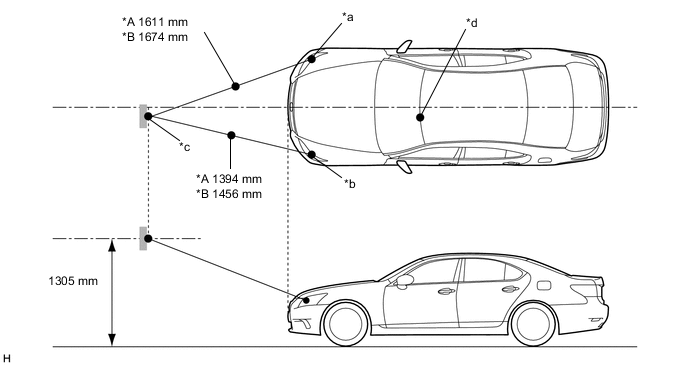
Text in Illustration *A HID Type Headlights *B LED Type Headlights *a Point R *b Point L *c Point T *d Night View Camera Location -
Once SST (laser radar adjusting reflector) is in place, remove the string.
-
-
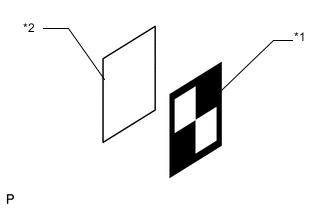
Text in Illustration *1 Target Sheet *2 Cardboard, etc. Attach the target sheet.
-
Attach the prepared target sheet to a piece of cardboard cut to the same size using double-sided tape.
Note
Do not attach reflective materials to the target face, as this may affect target recognition.
-
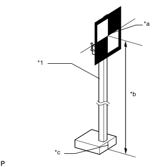
Text in Illustration *1 SST (Laser Radar Adjusting Reflector) *a Center of Target *b 1305 mm (4.28 ft.) *c Alignment Line Attach the target to SST (laser radar adjusting reflector), and then adjust the height of SST (laser radar adjusting reflector) so that the center of the target is at the height shown in the illustration.
Note
-
Perform this procedure as accurately as possible.
-
Attach the target sheet so that it is horizontal to the ground.
-
Make sure the center of the target and the alignment line of SST (laser radar adjusting reflector) are aligned.
-
-
-
-
ADJUST NIGHT VIEW CAMERA ASSEMBLY (for Automatic Adjustment)
Note
-
Close all doors.
-
Do not lean on the vehicle during the procedure.
-
Have one person sit in the driver seat and do not allow anyone else in the vehicle.
-
During adjustment, do not do anything that would make the vehicle tilt, such as allowing someone to exit or enter the vehicle, or loading or unloading luggage.
-
Turn the night view switch on, illuminate the headlights (it is necessary to cover the automatic light control sensor when this procedure is performed during the day), and make sure the target can be clearly seen on the accessory meter screen.
-
If the target cannot be clearly seen on the accessory meter screen, make the surrounding area brighter or move to a brighter area.
-
Once you confirm that the target can be clearly seen on the accessory meter screen, turn the night view switch off and turn the headlights off.
-
Do not turn on the clearance lights.
-
Make sure there are no light sources or reflective materials directed toward the night view camera within the hatched area shown in the illustration.
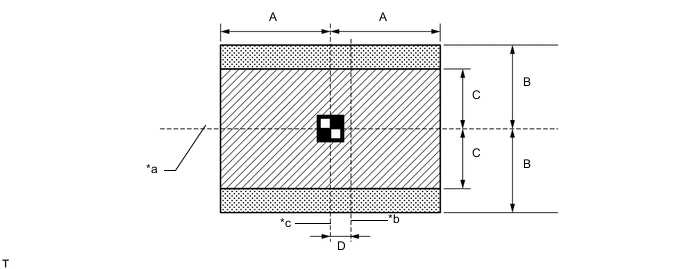
Text in Illustration *a Target Height *b Line extending from center point of vehicle *c Line extending from center point of camera - - Dimension Area Specification A 540 mm (21.3 in.) B 505 mm (19.9 in.) C 350 mm (13.8 in.) D 218 mm (8.58 in.)
-
Connect the GTS to the DLC3.
-
Turn the engine switch on (IG).
-
Turn the GTS on.
-
Clear all DTCs related to the No. 1 night view ECU Click here.
-
Select "Night View" from the display screen.
-
Select "Utility" from the display screen.
-
Select "Automatic Camera Adjustment" from the display screen.
-
Follow the instructions on the adjustment screen to perform automatic adjustment.
Note
The low beam headlights need to be left on until the headlight type is determined.
-
Check that a large, yellow frame is displayed around the camera image in the accessory meter indicating that the adjustment completed successfully.
Note
-
If DTCs are output after performing the adjustment even though no DTCs were output before the adjustment, the adjustment has not completed successfully. Therefore, check for DTCs after performing the adjustment Click here.
-
If DTCs are output, clear the DTCs Click here.
-
After clearing the DTCs, confirm the target position and perform automatic adjustment from the beginning.
-
-
If the automatic camera adjustment does not complete successfully, confirm the following items and perform automatic adjustment again.
Note
-
Make sure there are no black and white patterned objects in front of the vehicle.
-
To the extent that it is possible, use an area where the wall in front of the vehicle has no patterns.
-
Perform the adjustment in a place with no wind, and make sure there is a 4 m (13.1 ft.) or more x 3 m (9.84 ft.) or more level surface with no obstacles in front of the vehicle.
-
Make sure that no objects come between the target and vehicle (camera) during adjustment.
-
During adjustment, do not do anything that would make the vehicle tilt, such as allowing someone to exit or enter the vehicle, or loading or unloading luggage.
-
Check that there are no reflective materials in the surroundings or on the ground within a 4 m (13.1 ft.) or more x 3 m (9.84 ft.) or more area in front of the vehicle.
-
Perform the adjustment in a place where the ambient brightness does not change.
-
Do not turn on the headlights except for when the headlight type is being determined.
-
-
If the automatic camera adjustment does not complete successfully after a second attempt, perform manual camera adjustment.
-
-
ADJUST NIGHT VIEW CAMERA ASSEMBLY (for Manual Adjustment)
Note
-
Close all doors.
-
Do not lean on the vehicle during the vehicle.
-
Have one person sit in the driver seat and do not allow anyone else in the vehicle.
-
During adjustment, do not do anything that would make the vehicle tilt, such as allowing someone to exit or enter the vehicle, or loading or unloading luggage.
-
Turn the night view switch on, turn on the headlights (it is necessary to cover the automatic light control sensor when this procedure is performed during the day), and make sure the target can be clearly seen on the accessory meter screen.
-
If the target cannot be clearly seen on the accessory meter screen, make the surrounding area brighter or move to a bright area.
-
Once you confirm that the target can be clearly seen on the accessory meter screen, turn the night view switch off and turn the headlights off.
-
Do not turn on the clearance lights.
-
Make sure there are no light sources or reflective materials directed toward the night view camera within the hatched area shown in the illustration.
Text in Illustration *a Target Height *b Line extending from center point of vehicle *c Line extending from center point of camera - - Dimension Area Specification A 540 mm (21.3 in.) B 505 mm (19.9 in.) C 350 mm (13.8 in.) D 218 mm (8.58 in.)
-
Connect the GTS to the DLC3.
-
Turn the engine switch on (IG).
-
Turn the GTS on.
-
Clear all DTCs related to the No. 1 night view ECU Click here.
-
Select "Night View" from the display screen.
-
Select "Utility" from the display screen.
-
Select "Manual Camera Adjustment" from the display screen.
-
Follow the instructions on the adjustment screen to perform manual adjustment.
Note
-
The low beam headlights need to be left on until the headlight type is determined.
-
At the screen to adjust the vertical and horizontal position (the large adjustment screen), make sure that the target is within the specified area according to the judgment criteria specified later before proceeding. If you mistakenly proceed, start the adjustment from the beginning again.
-
The screen to adjust the vertical and horizontal position (the detailed adjustment screen) enters an infinite loop when the night view camera is malfunctioning (the adjustment amount cannot be properly registered). If the same screens appear several times, replace the night view camera.
-
When making adjustments, the outer adjustment frame and detailed adjustment crosshairs do not move. The entire displayed image, which includes the target, is moved.
-
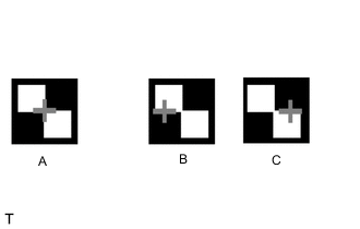
If the adjustment on the large adjustment screen is performed when adjusting the horizontal position, once all adjustments have been made, the crosshairs may be aligned with the horizontal line extending from the center of the target but not exactly in the center as shown in B and C of the illustration. However, even in this case, the adjustment is considered to have finished successfully. Even after performing the vertical adjustment on the large adjustment screen, perform the detailed adjustment.
-
-
Check that a large, yellow frame is displayed around the camera image in the accessory meter indicating that the adjustment completed successfully.
Note
-
If DTCs are output after performing the adjustment even though no DTCs were output before the adjustment, the adjustment has not completed successfully. Therefore, check for DTCs after performing the adjustment Click here
-
If DTCs are output, clear the DTCs Click here.
-
After clearing the DTCs, confirm the target position and perform automatic adjustment from the beginning.
-
-
Determine whether the center of the target is within the outer adjustment frame or aligned with the detailed adjustment crosshairs.
-
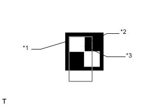
Text in Illustration *1 Target *2 Outer Adjustment Frame *3 Center of Target When making adjustments using the outer adjustment frame:
-
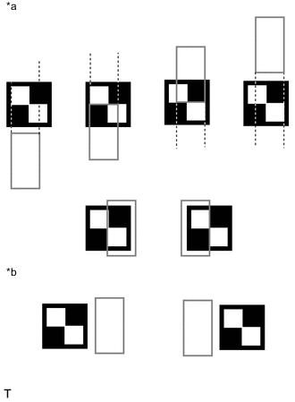
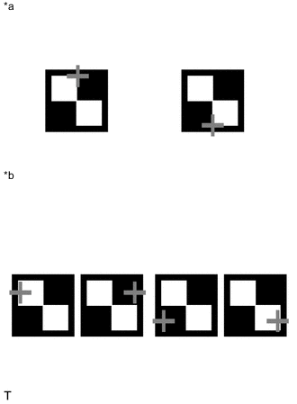
Text in Illustration *a Examples of white inner target area within 2 vertical lines of outer adjustment frame *b Examples of white inner target area not within 2 vertical lines of outer adjustment frame Make adjustments so that the center of the target is within the 2 vertical lines of the outer adjustment frame or within an extension of the 2 vertical lines (it is okay if the center of the target overlaps with the adjustment frame) (the "Adjustment of horizontal direction" screen).
Note
Even if the center of the target is not within the upper and lower edges of the outer adjustment frame, there is no problem as long as the center of the target is within an extension of the 2 vertical lines of the outer adjustment frame.
-
Text in Illustration *a Examples of white inner target area within 2 horizontal lines of outer adjustment frame *b Examples of white inner target area not within 2 horizontal lines of outer adjustment frame Make adjustments so that the center of the target is within the 2 horizontal lines of the outer adjustment frame (it is okay if the center of the target overlaps with the adjustment frame) (the "Adjustment of vertical direction" screen)
Note
Even if the center of the target is not within the left and right edges of the outer adjustment frame, there is no problem as long as the center of the target is within an extension of the 2 horizontal lines of the outer adjustment frame.
-
-
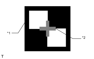
Text in Illustration *1 Target *2 Detailed Adjustment Crosshairs When making adjustments using the detailed adjustment frame:
-
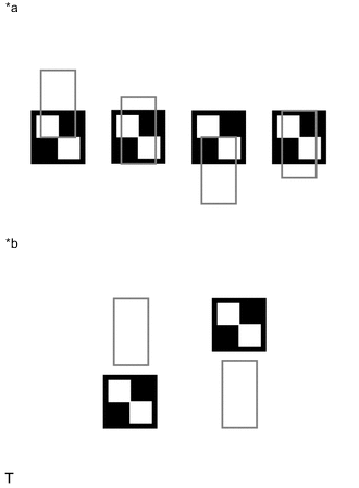
Text in Illustration *a Examples of white inner target area aligned with adjustment crosshairs *b Examples of white inner target area not aligned with adjustment crosshairs Make adjustments so that the center of the target overlaps with the detailed adjustment crosshairs or overlaps with an extension of the center of the target (the "Adjustment of horizontal direction" screen).
Note
Even if the center of the target does not overlap with the detailed adjustment crosshairs, there is no problem as long as the detailed adjustment crosshairs overlap with a vertical extension of the center of the target.
-
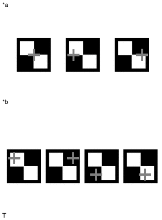
Text in Illustration *a Examples of white inner target area aligned with adjustment crosshairs *b Examples of white inner target area not aligned with adjustment crosshairs Make adjustments so that the center of the target overlaps with the detailed adjustment crosshairs or overlaps with an extension of the center of the target (the "Adjustment of vertical direction" screen).
Note
Even if the center of the target does not overlap with the detailed adjustment crosshairs, there is no problem as long as the detailed adjustment crosshairs overlap with a horizontal extension of the center of the target.
-
-
-