LEXUS PARKING ASSIST-SENSOR SYSTEM Clearance Sonar Main Switch Circuit
DESCRIPTION
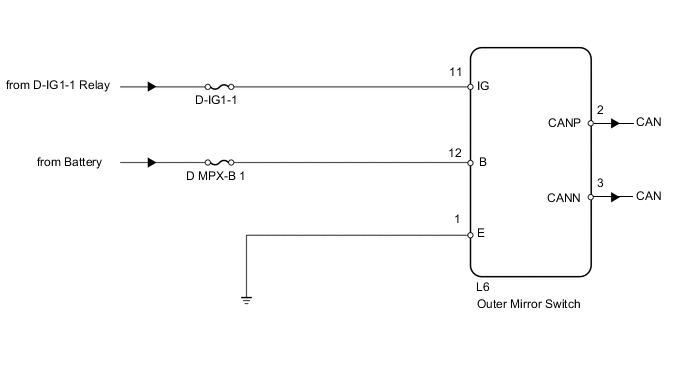
The clearance sonar main switch is installed in the outer mirror switch assembly. When the clearance sonar main switch turns ON, the ON signal is input into the ECU through the CAN communication line.
WIRING DIAGRAM
PROCEDURE
-
READ VALUE USING INTELLIGENT TESTER (MAIN SWITCH)
-
Use the Data List to check if the clearance sonar main switch is functioning properly.
Clearance Sonar Tester Display Measurement Item/Range Normal Condition Diagnostic Note Main Switch Clearance sonar main switch/OFF or ON OFF: Clearance sonar main switch OFF
ON: Clearance sonar main switch ON
-
OK 
PROCEED TO NEXT CIRCUIT INSPECTION SHOWN IN PROBLEM SYMPTOMS TABLE Click here
NG 
-
-
CHECK FUSE (D-IG1-1, D MPX-B 1)
-
Remove the D-IG1-1 and D MPX-B 1 fuses from the driver side junction block.
-
Measure the resistance according to the value(s) in the table below.
Standard resistance Tester Connection Condition Specified Condition D-IG1-1 Always Below 1 Ω D MPX-B 1 Always Below 1 Ω
NG
REPLACE FUSE
OK
-
-
CHECK HARNESS AND CONNECTOR (OUTER MIRROR SWITCH POWER SUPPLY)
-
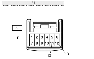
*1 Front view of wire harness connector: (to Outer Mirror Switch) Disconnect the switch connector.
-
Measure the resistance according to the value(s) in the table below.
Standard resistance Tester Connection Condition Specified Condition L6-1 (E) - Body ground Always Below 1 Ω -
Measure the voltage according to the value(s) in the table below.
Standard voltage Tester Connection Condition Specified Condition L6-12 (B) - Body ground Always 11 to 14 V L6-11 (IG) - Body ground Engine switch on (IG) 11 to 14 V
OK
PROCEED TO NEXT CIRCUIT INSPECTION SHOWN IN PROBLEM SYMPTOMS TABLE Click here
NG
REPAIR OR REPLACE HARNESS OR CONNECTOR
-