TELEMATICS SYSTEM(w/ Telematics Transceiver for G-BOOK) TERMINALS OF ECU
Tech Tips
Check from the rear of the connector while it is connected to the components.
-
TELEMATICS TRANSCEIVER
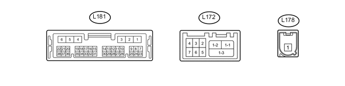
Terminal No. (Symbol) Wiring Color Terminal Description Condition Specified Condition L181-1 (+B) - L181-4 (E) R - B Power source (+B) Always 11 to 14 V L181-2 (SPI+) - L181-4 (E) L - B Sound signal Audio system playing A waveform synchronized with sound is output L181-3 (SPI-) - L181-4 (E) LG - B Sound signal Audio system playing A waveform synchronized with sound is output L181-4 (E) - Body ground B - Body ground Ground Always Below 1 V L181-5 (SPO+) - L181-4 (E) V - B Sound signal Emergency call mode A waveform synchronized with the received voice is output L181-6 (SPO-) - L181-4 (E) P - B Sound signal Emergency call mode A waveform synchronized with the received voice is output L181-7 (IG2) - L181-4 (E) R - B Power source (IG) Engine switch on (IG) 11 to 14 V Engine switch off Below 1 V L181-8 (ACC) - L181-4 (E) LG - B Power source (ACC) Engine switch on (ACC) 11 to 14 V Engine switch off Below 1 V L181-11 (IND1) - L181-4 (E) LG - B Emergency call switch red indicator illumination signal For 5 seconds after turning the engine switch on (ACC) 1 to 8.5 V Engine switch off Below 1 V L181-12 (IND2) - L181-4 (E) L - B Emergency call switch green indicator illumination signal For 5 seconds after turning the engine switch on (ACC) 1 to 8.5 V Engine switch off Below 1 V L181-15 (CANP) R CAN communication signal - - L181-16 (CANN) G CAN communication signal - - L181-17 (MUTE) - L181-4 (E) SB - B Mute Signal Audio system playing Above 3.5 V Emergency call mode Below 1 V L181-18 (MCO+) - L181-4 (E) Y - B Microphone voice signal Refer to "Microphone Check" Click here
- L181-19 (MCO-) - L181-4 (E) BR - B Microphone voice signal Refer to "Microphone Check" Click here
- L181-24 (GSW) - L181-4 (E) L - B Airbag deployment signal Engine switch on (IG) Pulse generation
(Refer to waveform 1)
L181-26 (SIG-) - L181-4 (E) G - B Ground Always Below 1 V L181-27 (SIG1) - L181-26 (SIG-) P - G Emergency call switch button condition signal Emergency call switch not pressed 1.3 to 1.9 V Emergency call switch pressed 0.5 to 0.8 V L181-32 (SGND) - L181-4 (E) Shield - B Shield ground Always Below 1 V L181-33 (MCVD) - L181-4 (E) B - B Telephone microphone assembly power supply Engine switch on (ACC) 4 to 6 V Engine switch off Below 1 V L181-34 (MCI+) - L181-4 (E) W - B Microphone voice signal Refer to "Microphone Check" Click here
- L181-35 (MCI-) - L181-4 (E) R - B Microphone voice signal Refer to "Microphone Check" Click here
- L172-1-1 (USB-) - USB communication line - - L172-1-2 (USB+) - USB communication line - - L172-1-3 (USBS) - Body ground Shield - Body ground Shield ground Always Below 1 V L172-2 (USBG) - Body ground W - Body ground Shield ground Always Below 1 V L172-3 (VOT+) - L181-4 (E) G - B Receive voice signal Receiving a call while using the operator service A waveform synchronized with the received voice is output L172-4 (USBV) - L181-4 (E) W - B Telephone microphone assembly power supply Engine switch on (ACC) 4.75 to 5.25 V Engine switch off Below 1 V L172-5 (VOT-) - L181-4 (E) B - B Receive voice signal Receiving a call while using the operator service A waveform synchronized with the received voice is output L172-6 (VOR-) - L181-4 (E) R - B Sent voice signal Calling while using the operator service A waveform synchronized with the sent voice is output L172-7 (VOR+) - L181-4 (E) W - B Sent voice signal Calling while using the operator service A waveform synchronized with the sent voice is output
-
Reference (Oscilloscope waveform):
-
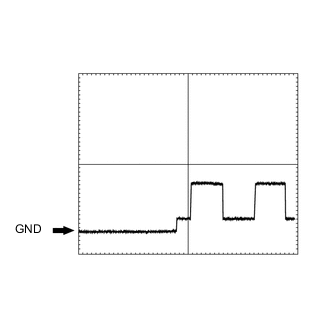
Waveform 1
Item Condition Tester Connection L181-24 (GSW) - L181-4 (E) Tool setting 5.0 V/DIV., 20 ms/DIV. Vehicle condition Engine switch on (IG)
-
-
-
MULTI-MEDIA MODULE RECEIVER ASSEMBLY Click here