REAR SEAT ENTERTAINMENT SYSTEM TERMINALS OF ECU
-
CHECK DISC PLAYER ASSEMBLY

Text in Illustration *A for 4-passengerr with Ottoman *B except 4-passengerr with Ottoman Tech Tips
Perform the check from the rear of the connector while it is connected to the disc player assembly.
for 4-passengerr with Ottoman Terminal No. (Symbol) Wiring Color Terminal Description Condition Specified Condition z17-1 (L-) - z17-13 (GND) # - # Sound signal Disc player assembly playing Waveform synchronized with sound signal is output z17-2 (L+) - z17-13 (GND) # - # Sound signal Disc player assembly playing Waveform synchronized with sound signal is output z17-3 (R-) - z17-13 (GND) # - # Sound signal Disc player assembly playing Waveform synchronized with sound signal is output z17-4 (R+) - z17-13 (GND) # - # Sound signal Disc player assembly playing Waveform synchronized with sound signal is output z17-5 (SLD) - z17-13 (GND) Shielded - # Shield ground Always Below 1 Ω z17-6 (MUTE) - z17-13 (GND) # - # Mute signal RSE playing → Source changed Higher than 3.5 V → Below 1 V z17-7 (ACC) - z17-13 (GND) # - # Power supply for television display assembly Engine switch on (ACC) 11 to 14 V Engine switch off Below 1 V z17-8 (+B) - z17-13 (GND) # - # Battery Always 11 to 14 V z17-9 (TX+) # AVC-LAN communication signal - - z17-10 (TX-) # AVC-LAN communication signal - - z17-13 (GND) - Body ground # - Body ground Ground Always Below 1 Ω z20 (HDMI) # HDMI communication signal - -
-
#: There is no wire color information
except 4-passengerr with Ottoman, Terminal No. (Symbol) Wiring Color Terminal Description Condition Specified Condition R90-1 (L-) - R90-13 (GND) W - W-B Sound signal Disc player assembly playing Waveform synchronized with sound signal is output R90-2 (L+) - R90-13 (GND) B - W-B Sound signal Disc player assembly playing Waveform synchronized with sound signal is output R90-3 (R-) - R90-13 (GND) R - W-B Sound signal Disc player assembly playing Waveform synchronized with sound signal is output R90-4 (R+) - R90-13 (GND) G - W-B Sound signal Disc player assembly playing Waveform synchronized with sound signal is output R90-5 (SLD) - R90-13 (GND) Shielded - W-B Shield ground Always Below 1 Ω R90-6 (MUTE) - R90-13 (GND) V - W-B Mute signal RSE playing → Source changed Higher than 3.5 V → Below 1 V R90-7 (ACC) - R90-13 (GND) G - W-B Power supply for television display assembly Engine switch on (ACC) 11 to 14 V Engine switch off Below 1 V R90-8 (+B) - R90-13 (GND) V - W-B Battery Always 11 to 14 V R90-9 (TX+) Y AVC-LAN communication signal - - R90-10 (TX-) B AVC-LAN communication signal - - R90-13 (GND) - Body ground W-B - Body ground Ground Always Below 1 Ω R95 (HDMI) # HDMI communication signal - - -
-
CHECK TELEVISION DISPLAY ASSEMBLY
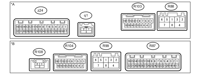
Text in Illustration *A for Roof *B for Center Console Side Tech Tips
Perform the check from the rear of the connector while it is connected to the television display assembly.
for Roof Terminal No. (Symbol) Wiring Color Terminal Description Condition Specified Condition z24-1 (+B) - z24-3 (GND) B - W-B Battery Always 11 to 14 V z24-3 (GND) - Body ground W-B - Body ground Ground Always Below 1 Ω z24-4 (TX2+) LG AVC-LAN communication signal - - z24-5 (TX2-) BE AVC-LAN communication signal - - z24-6 (HP1R) - z24-3 (GND) SB - W-B RSE sound signal RSE playing Waveform synchronized with sound is output z24-7 (SLD5) - z24-3 (GND) Shielded - W-B Shield ground Always Below 1 Ω z24-8 (HP1L) - z24-3 (GND) V - W-B RSE sound signal RSE playing Waveform synchronized with sound is output z24-10 (R2+) - z24-3 (GND) G - W-B Sound signal Disc player assembly playing Waveform synchronized with sound signal is output z24-11 (R2-) - z24-3 (GND) B - W-B Sound signal Disc player assembly playing Waveform synchronized with sound signal is output z24-12 (L2+) - z24-3 (GND) R - W-B Sound signal Disc player assembly playing Waveform synchronized with sound signal is output z24-13 (L2-) - z24-3 (GND) W - W-B Sound signal Disc player assembly playing Waveform synchronized with sound signal is output z24-14 (R+) - z24-3 (GND) P - W-B Sound signal External device playing Waveform synchronized with sound signal is output z24-15 (SGN3) - z24-3 (GND) L - W-B Shield signal ground Always Below 100 Ω z24-16 (L+) - z24-3 (GND) G - W-B Sound signal External device playing Waveform synchronized with sound signal is output z24-17 (+B2) - z24-3 (GND) W - W-B Battery Always 11 to 14 V z24-19 (GND2) - Body ground BR - Body ground Ground Always Below 1 Ω z24-20 (TX3+) G AVC-LAN communication signal - - z24-21 (TX3-) L AVC-LAN communication signal - - z24-22 (HP2R) - z24-3 (GND) G - W-B RSE sound signal RSE playing Waveform synchronized with sound is output z24-23 (SLD6) - z24-3 (GND) Shielded - W-B Shield ground Always Below 1 Ω z24-24 (HP2L) - z24-3 (GND) R - W-B RSE sound signal RSE playing Waveform synchronized with sound is output z24-26 (MUT2) - z24-3 (GND) Y - W-B Mute signal Disc player assembly playing → Source changed Higher than 3.5 V → Below 1 V z24-27 (ADPI) - z24-3 (GND) SB - W-B Video terminal ground Always Below 1 V z24-28 (VMTR) - z24-3 (GND) V - W-B Mute signal RSE playing → Source changed 2 V or higher → Below 0.7 V → 2 V or higher z24-29 (SGN6) - z24-3 (GND) Shielded - W-B Shield ground Always Below 1 Ω z24-30 (SGN5) - z24-3 (GND) Shielded - W-B Shield ground Always Below 1 Ω z24-32 (VD) - z24-31 (VG) Y - BR Display signal External device playing, VTR displayed Waveform synchronized with display signal is output R88-2 (MI+) B MOST communication signal - - R88-3 (MI-) B MOST communication signal - - R88-4 (SLDI) - Body ground Shielded - Body ground Shield ground Always Below 1 Ω R88-5 (MO+) B MOST communication signal - - R88-6 (MO-) B MOST communication signal - - R88-7 (SLDO) - Body ground Shielded - Body ground Shield ground Always Below 1 Ω R88-8 (WUI) - z24-3 (GND) W - W-B MOST communication wake up signal
(Input)
Engine switch on (ACC) 4.5 V or higher Engine switch off Below 1 V R103 (TM2+) # HDMI communication signal - - q1-1 (GVI+) # GVIF communication signal - - q1-2 (GVI-) # GVIF communication signal - - q1-3 (GVG1) # GVIF communication signal - -
-
#: There is no wire color information.
for Center Console Side Terminal No. (Symbol) Wiring Color Terminal Description Condition Specified Condition R87-1 (+B) - R87-3 (GND) V - W-B Battery Always 11 to 14 V R87-3 (GND) - Body ground W-B - Body ground Ground Always Below 1 Ω R87-4 (TX2+) Y AVC-LAN communication signal - - R87-5 (TX2-) B AVC-LAN communication signal - - R87-6 (HP1R) - R87-3 (GND) B - W-B RSE sound signal RSE playing Waveform synchronized with sound is output R87-7 (SLD5) - R87-3 (GND) Shielded - W-B Shield ground Always Below 1 Ω R87-8 (HP1L) - R87-3 (GND) W - W-B RSE sound signal RSE playing Waveform synchronized with sound is output R87-10 (R2+) - R87-3 (GND) G - W-B Sound signal Disc player assembly playing Waveform synchronized with sound signal is output R87-11 (R2-) - R87-3 (GND) R - W-B Sound signal Disc player assembly playing Waveform synchronized with sound signal is output R87-12 (L2+) - R87-3 (GND) B - W-B Sound signal Disc player assembly playing Waveform synchronized with sound signal is output R87-13 (L2-) - R87-3 (GND) W - W-B Sound signal Disc player assembly playing Waveform synchronized with sound signal is output R87-14 (R+) - R87-3 (GND) W - W-B Sound signal External device playing Waveform synchronized with sound signal is output R87-15 (SGN3) - R87-3 (GND) R - W-B Shield signal ground Always Below 100 Ω R87-16 (L+) - R87-3 (GND) B - W-B Sound signal External device playing Waveform synchronized with sound signal is output R87-17 (+B2) - R87-3 (GND) P - W-B Battery Always 11 to 14 V R87-19 (GND2) - Body ground W-B - Body ground Ground Always Below 1 Ω R87-20 (TX3+) R AVC-LAN communication signal - - R87-21 (TX3-) G AVC-LAN communication signal - - R87-22 (HP2R) - R87-3 (GND) BR - W-B RSE sound signal RSE playing Waveform synchronized with sound is output R87-23 (SLD6) - R87-3 (GND) Shielded - W-B Shield ground Always Below 1 Ω R87-24 (HP2L) - R87-3 (GND) Y - W-B RSE sound signal RSE playing Waveform synchronized with sound is output R87-26 (MUT2) - R87-3 (GND) V - W-B Mute signal Disc player assembly playing → Source changed Higher than 3.5 V → Below 1 V R87-27 (ADPI) - R87-3 (GND) L - W-B Video terminal ground Always Below 1 V R87-28 (VMTR) - R87-3 (GND) BE - W-B Mute signal RSE playing → Source changed 2 V or higher → Below 0.7 V → 2 V or higher R87-29 (SGN6) - R87-3 (GND) Shielded - W-B Shield ground Always Below 1 Ω R87-30 (SGN5) - R87-3 (GND) Shielded - W-B Shield ground Always Below 1 Ω R87-32 (VD) - R87-31 (VG) Y - BR Display signal External device playing, VTR displayed Waveform synchronized with display signal is output R99-2 (MI+) B MOST communication signal - - R99-3 (MI-) B MOST communication signal - - R99-4 (SLDI) - Body ground Shielded - Body ground Shield ground Always Below 1 Ω R99-5 (MO+) B MOST communication signal - - R99-6 (MO-) B MOST communication signal - - R99-7 (SLDO) - Body ground Shielded - Body ground Shield ground Always Below 1 Ω R99-8 (WUI) - R87-3 (GND) W - W-B MOST communication wake up signal
(Input)
Engine switch on (ACC) 4.5 V or higher Engine switch off Below 1 V R104 (TM2+) # HDMI communication signal - - R108-1 (GVI+) # GVIF communication signal - - R108-2 (GVI-) # GVIF communication signal - - R108-3 (GVG1) # GVIF communication signal - -
-
#: There is no wire color information.
-
-
CHECK MULTI-DISPLAY CONTROLLER SUB-ASSEMBLY
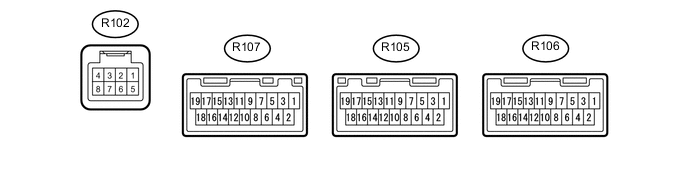
Tech Tips
Perform the check from the rear of the connector while it is connected to the multi-display controller sub-assembly.
Terminal No. (Symbol) Wiring Color Terminal Description Condition Specified Condition R102-1 (TX+) R AVC-LAN communication signal - - R102-2 (TX-) G AVC-LAN communication signal - - R102-4 (+B) - R102-6 (GND2) G - W-B Battery Always 11 to 14 V R102-5 (GND) - Body ground R - Body ground Ground Always Below 1 Ω R102-6 (GND2) - Body ground W-B - Body ground Ground Always Below 1 Ω R102-8 (ACC) - R102-6 (GND2) L - W-B Power supply for multi-display controller sub-assembly Engine switch on (ACC) 11 to 14 V Engine switch off Below 1 V R105 (IN) # HDMI communication signal - - R106 (BD) # HDMI communication signal - - R107 (OUT) # HDMI communication signal - -
-
#: There is no wire color information.
-
-
CHECK MULTI-MEDIA MODULE RECEIVER ASSEMBLY Click here
-
CHECK STEREO COMPONENT AMPLIFIER ASSEMBLY Click here