AUDIO AND VISUAL SYSTEM Speaker Circuit
DESCRIPTION
If there is a short in a speaker circuit, the stereo component amplifier assembly detects it and stops output to the speakers.
Thus sound cannot be heard from the speakers even if there is no malfunction in the stereo component amplifier assembly, DCM (telematics transceiver)* or speakers.
*: w/ Telematics Transceiver
WIRING DIAGRAM
CAUTION / NOTICE / HINT
Note
Depending on the parts that are replaced during vehicle inspection or maintenance, performing initialization, registration or calibration may be needed. Refer to Precaution for Navigation System.
PROCEDURE
-
CHECK VEHICLE TYPE
-
Check the vehicle type.
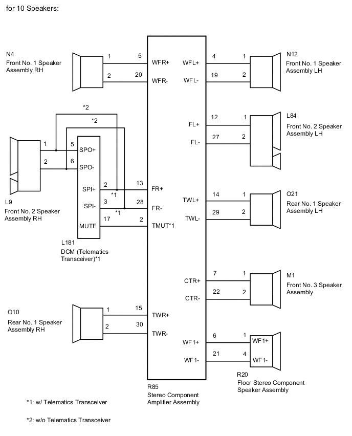
Model Model Proceed to for 10 Speakers A for 19 Speakers B
B 
CHECK HARNESS AND CONNECTOR (SPEAKER CIRCUIT) Click here
A 
-
-
CHECK HARNESS AND CONNECTOR (SPEAKER CIRCUIT)
-
*1: for RH Side
-
*2: for LH Side
-
*3: w/ Telematics Transceiver
-
Disconnect the R85 stereo component amplifier assembly connector.
-
Disconnect the N4*1 and/or N12*2 front No. 1 speaker assembly connector.
-
Disconnect the L9*1 and/or L84*2 front No. 2 speaker assembly connector.
-
Disconnect the M1 front No. 3 speaker assembly connector.
-
Disconnect the O10*1 and/or O21*2 rear No. 1 speaker assembly connector.
-
Disconnect the R20 floor stereo component speaker assembly connector.
-
Disconnect the L181 DCM (telematics transceiver) connector.*3
-
Measure the resistance according to the value(s) in the table below.
Standard Resistance for RH Side (w/ Telematics Transceiver) Tester Connection Condition Specified Condition R85-5 (WFR+) - N4-1 Always Below 1 Ω R85-20 (WFR-) - N4-2 Always Below 1 Ω R85-13 (FR+) - L181-2 (SPI+) Always Below 1 Ω R85-28 (FR-) - L181-3 (SPI-) Always Below 1 Ω R85-2 (TMUT) - L181-17 (MUTE) Always Below 1 Ω L181-5 (SPO+) - L9-1 Always Below 1 Ω L181-6 (SPO-) - L9-2 Always Below 1 Ω R85-15 (TWR+) - O10-1 Always Below 1 Ω R85-30 (TWR-) - O10-2 Always Below 1 Ω R85-5 (WFR+) - Body ground Always 10 kΩ or higher R85-20 (WFR-) - Body ground Always 10 kΩ or higher R85-13 (FR+) - Body ground Always 10 kΩ or higher R85-28 (FR-) - Body ground Always 10 kΩ or higher R85-2 (TMUT) - Body ground Always 10 kΩ or higher L181-5 (SPO+) - Body ground Always 10 kΩ or higher L181-6 (SPO-) - Body ground Always 10 kΩ or higher R85-15 (TWR+) - Body ground Always 10 kΩ or higher R85-30 (TWR-) - Body ground Always 10 kΩ or higher for RH Side (w/o Telematics Transceiver): Tester Connection Condition Specified Condition R85-5 (WFR+) - N4-1 Always Below 1 Ω R85-20 (WFR-) - N4-2 Always Below 1 Ω R85-13 (FR+) - L9-1 Always Below 1 Ω R85-28 (FR-) - L9-2 Always Below 1 Ω R85-15 (TWR+) - O10-1 Always Below 1 Ω R85-30 (TWR-) - O10-2 Always Below 1 Ω R85-5 (WFR+) - Body ground Always 10 kΩ or higher R85-20 (WFR-) - Body ground Always 10 kΩ or higher R85-13 (FR+) - Body ground Always 10 kΩ or higher R85-28 (FR-) - Body ground Always 10 kΩ or higher R85-15 (TWR+) - Body ground Always 10 kΩ or higher R85-30 (TWR-) - Body ground Always 10 kΩ or higher for LH Side: Tester Connection Condition Specified Condition R85-4 (WFL+) - N12-1 Always Below 1 Ω R85-19 (WFL-) - N12-2 Always Below 1 Ω R85-12 (FL+) - L84-1 Always Below 1 Ω R85-27 (FL-) - L84-2 Always Below 1 Ω R85-14 (TWL+) - O21-1 Always Below 1 Ω R85-29 (TWL-) - O21-2 Always Below 1 Ω R85-4 (WFL+) - Body ground Always 10 kΩ or higher R85-19 (WFL-) - Body ground Always 10 kΩ or higher R85-12 (FL+) - Body ground Always 10 kΩ or higher R85-27 (FL-) - Body ground Always 10 kΩ or higher R85-14 (TWL+) - Body ground Always 10 kΩ or higher R85-29 (TWL-) - Body ground Always 10 kΩ or higher for Center Side: Tester Connection Condition Specified Condition R85-7 (CTR+) - M1-1 Always Below 1 Ω R85-22 (CTR-) - M1-2 Always Below 1 Ω R85-6 (WF1+) - R20-1 (WF1+) Always Below 1 Ω R85-21 (WF1-) - R20-4 (WF1-) Always Below 1 Ω R85-7 (CTR+) - Body ground Always 10 kΩ or higher R85-22 (CTR-) - Body ground Always 10 kΩ or higher R85-6 (WF1+) - Body ground Always 10 kΩ or higher R85-21 (WF1-) - Body ground Always 10 kΩ or higher Result Proceed to OK NG
NG 
REPAIR OR REPLACE HARNESS OR CONNECTOR
OK
-
-
INSPECT FRONT NO. 1 SPEAKER ASSEMBLY
-
Remove the front No. 1 speaker assembly.
-
Inspect the front No. 1 speaker assembly.
Result Proceed to OK NG
NG
REPLACE FRONT NO. 1 SPEAKER ASSEMBLY Click here
OK
-
-
INSPECT FRONT NO. 2 SPEAKER ASSEMBLY
-
Remove the front No. 2 speaker assembly.
-
Inspect the front No. 2 speaker assembly.
Result Proceed to OK NG
NG
REPLACE FRONT NO. 2 SPEAKER ASSEMBLY Click here
OK
-
-
INSPECT FRONT NO. 3 SPEAKER ASSEMBLY
-
Remove the front No. 3 speaker assembly.
-
Inspect the front No. 3 speaker assembly.
Result Proceed to OK NG
NG
REPLACE FRONT NO. 3 SPEAKER ASSEMBLY Click here
OK
-
-
INSPECT REAR NO. 1 SPEAKER ASSEMBLY
-
Remove the rear No. 1 speaker assembly.
for Standard Body: Click here
for Long Body: Click here
-
Inspect the rear No. 1 speaker assembly.
for Standard Body: Click here
for Long Body: Click here
Result Proceed to OK NG
NG
REPLACE REAR NO. 1 SPEAKER ASSEMBLY for Standard Body: Click here
REPLACE REAR NO. 1 SPEAKER ASSEMBLY for Long Body: Click hereOK
-
-
INSPECT FLOOR STEREO COMPONENT SPEAKER ASSEMBLY
-
Remove the floor stereo component speaker assembly.
-
Inspect the floor stereo component speaker assembly.
Result Result Proceed to OK (w/ Telematics Transceiver) A OK (w/o Telematics Transceiver) B NG C
B
REPLACE STEREO COMPONENT AMPLIFIER ASSEMBLY Click here
C
REPLACE FLOOR STEREO COMPONENT SPEAKER ASSEMBLY Click here
A
-
-
CHECK DCM (TELEMATICS TRANSCEIVER)
-
Replace the DCM (telematics transceiver) with a new one.
-
Check the malfunction disappears.
OK Malfunction disappears. Result Proceed to OK NG
OK
END (DCM [TELEMATICS TRANSCEIVER] IS DEFECTIVE)
NG
REPLACE STEREO COMPONENT AMPLIFIER ASSEMBLY Click here
-
-
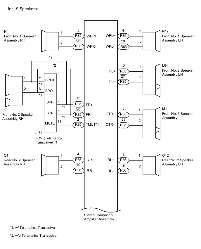
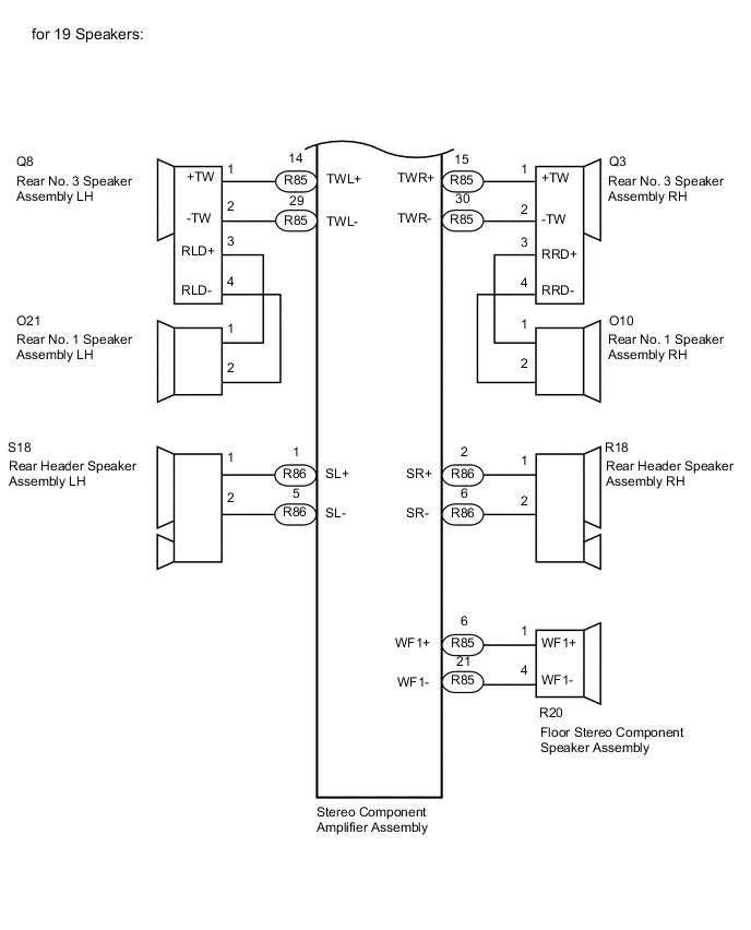
CHECK HARNESS AND CONNECTOR (SPEAKER CIRCUIT)
-
*1: for RH Side
-
*2: for LH Side
-
*3: w/ Telematics Transceiver
-
Disconnect the R85 stereo component amplifier assembly connector.
-
Disconnect the N4*1 and/or N12*2 front No. 1 speaker assembly connector.
-
Disconnect the L9*1 and/or L84*2 front No. 2 speaker assembly connector.
-
Disconnect the M1 front No. 3 speaker assembly connector.
-
Disconnect the O10*1 and/or O21*2 rear No. 1 speaker assembly connector.
-
Disconnect the O1*1 and/or O12*2 rear No. 2 speaker assembly connector.
-
Disconnect the Q3*1 and/or Q8*2 rear No. 3 speaker assembly connector.
-
Disconnect the R18*1 and/or S18*2 rear header speaker assembly connector.
-
Disconnect the R20 floor stereo component speaker assembly connector.
-
Disconnect the L181 DCM (telematics transceiver) connector.*3
-
Measure the resistance according to the value(s) in the table below.
Standard Resistance for RH Side (w/ Telematics Transceiver) Tester Connection Condition Specified Condition R85-5 (WFR+) - N4-1 Always Below 1 Ω R85-20 (WFR-) - N4-2 Always Below 1 Ω R85-13 (FR+) - L181-2 (SPI+) Always Below 1 Ω R85-28 (FR-) - L181-3 (SPI-) Always Below 1 Ω R85-2 (TMUT) - L181-17 (MUTE) Always Below 1 Ω L181-5 (SPO+) - L9-1 Always Below 1 Ω L181-6 (SPO-) - L9-2 Always Below 1 Ω R86-4 (RR+) - O1-1 Always Below 1 Ω R86-10 (RR-) - O1-2 Always Below 1 Ω R85-15 (TWR+) - Q3-1 (+TW) Always Below 1 Ω R85-30 (TWR-) - Q3-2 (-TW) Always Below 1 Ω Q3-3 (RRD+) - O10-1 Always Below 1 Ω Q3-4 (RRD-) - O10-2 Always Below 1 Ω R86-2 (SR+) - R18-1 Always Below 1 Ω R86-6 (SR-) - R18-2 Always Below 1 Ω R85-5 (WFR+) - Body ground Always 10 kΩ or higher R85-20 (WFR-) - Body ground Always 10 kΩ or higher R85-13 (FR+) - Body ground Always 10 kΩ or higher R85-28 (FR-) - Body ground Always 10 kΩ or higher R85-2 (TMUT) - Body ground Always 10 kΩ or higher L181-5 (SPO+) - Body ground Always 10 kΩ or higher L181-6 (SPO-) - Body ground Always 10 kΩ or higher R86-4 (RR+) - Body ground Always 10 kΩ or higher R86-10 (RR-) - Body ground Always 10 kΩ or higher R85-15 (TWR+) - Body ground Always 10 kΩ or higher R85-30 (TWR-) - Body ground Always 10 kΩ or higher Q3-3 (RRD+) - Body ground Always 10 kΩ or higher Q3-4 (RRD-) - Body ground Always 10 kΩ or higher R86-2 (SR+) - Body ground Always 10 kΩ or higher R86-6 (SR-) - Body ground Always 10 kΩ or higher for RH Side (w/o Telematics Transceiver): Tester Connection Condition Specified Condition R85-5 (WFR+) - N4-1 Always Below 1 Ω R85-20 (WFR-) - N4-2 Always Below 1 Ω R85-13 (FR+) - L9-1 Always Below 1 Ω R85-28 (FR-) - L9-2 Always Below 1 Ω R86-4 (RR+) - O1-1 Always Below 1 Ω R86-10 (RR-) - O1-2 Always Below 1 Ω R85-15 (TWR+) - Q3-1 (+TW) Always Below 1 Ω R85-30 (TWR-) - Q3-2 (-TW) Always Below 1 Ω Q3-3 (RRD+) - O10-1 Always Below 1 Ω Q3-4 (RRD-) - O10-2 Always Below 1 Ω R86-2 (SR+) - R18-1 Always Below 1 Ω R86-6 (SR-) - R18-2 Always Below 1 Ω R85-5 (WFR+) - Body ground Always 10 kΩ or higher R85-20 (WFR-) - Body ground Always 10 kΩ or higher R85-13 (FR+) - Body ground Always 10 kΩ or higher R85-28 (FR-) - Body ground Always 10 kΩ or higher R86-4 (RR+) - Body ground Always 10 kΩ or higher R86-10 (RR-) - Body ground Always 10 kΩ or higher R85-15 (TWR+) - Body ground Always 10 kΩ or higher R85-30 (TWR-) - Body ground Always 10 kΩ or higher Q3-3 (RRD+) - Body ground Always 10 kΩ or higher Q3-4 (RRD-) - Body ground Always 10 kΩ or higher R86-2 (SR+) - Body ground Always 10 kΩ or higher R86-6 (SR-) - Body ground Always 10 kΩ or higher for LH Side: Tester Connection Condition Specified Condition R85-4 (WFL+) - N12-1 Always Below 1 Ω R85-19 (WFL-) - N12-2 Always Below 1 Ω R85-12 (FL+) - L84-1 Always Below 1 Ω R85-27 (FL-) - L84-2 Always Below 1 Ω R86-3 (RL+) - O12-1 Always Below 1 Ω R86-9 (RL-) - O12-2 Always Below 1 Ω R85-14 (TWL+) - Q8-1 (+TW) Always Below 1 Ω R85-29 (TWL-) - Q8-2 (-TW) Always Below 1 Ω Q8-3 (RLD+) - O21-1 Always Below 1 Ω Q8-4 (RLD-) - O21-2 Always Below 1 Ω R86-1 (SL+) - S18-1 Always Below 1 Ω R86-5 (SL-) - S18-2 Always Below 1 Ω R85-4 (WFL+) - Body ground Always 10 kΩ or higher R85-19 (WFL-) - Body ground Always 10 kΩ or higher R85-12 (FL+) - Body ground Always 10 kΩ or higher R85-27 (FL-) - Body ground Always 10 kΩ or higher R86-3 (RL+) - Body ground Always 10 kΩ or higher R86-9 (RL-) - Body ground Always 10 kΩ or higher R85-14 (TWL+) - Body ground Always 10 kΩ or higher R85-29 (TWL-) - Body ground Always 10 kΩ or higher Q8-3 (RLD+) - Body ground Always 10 kΩ or higher Q8-4 (RLD-) - Body ground Always 10 kΩ or higher R86-1 (SL+) - Body ground Always 10 kΩ or higher R86-5 (SL-) - Body ground Always 10 kΩ or higher for Center Side: Tester Connection Condition Specified Condition R85-7 (CTR+) - M1-1 Always Below 1 Ω R85-22 (CTR-) - M1-2 Always Below 1 Ω R85-6 (WF1+) - R20-1 (WF1+) Always Below 1 Ω R85-21 (WF1-) - R20-4 (WF1-) Always Below 1 Ω R85-7 (CTR+) - Body ground Always 10 kΩ or higher R85-22 (CTR-) - Body ground Always 10 kΩ or higher R85-6 (WF1+) - Body ground Always 10 kΩ or higher R85-21 (WF1-) - Body ground Always 10 kΩ or higher Result Proceed to OK NG
NG
REPAIR OR REPLACE HARNESS OR CONNECTOR
OK
-
-
INSPECT FRONT NO. 1 SPEAKER ASSEMBLY
-
Remove the front No. 1 speaker assembly.
-
Inspect the front No. 1 speaker assembly.
Result Proceed to OK NG
NG
REPLACE FRONT NO. 1 SPEAKER ASSEMBLY Click here
OK
-
-
INSPECT FRONT NO. 2 SPEAKER ASSEMBLY
-
Remove the front No. 2 speaker assembly.
-
Inspect the front No. 2 speaker assembly.
Result Proceed to OK NG
NG
REPLACE FRONT NO. 2 SPEAKER ASSEMBLY Click here
OK
-
-
INSPECT FRONT NO. 3 SPEAKER ASSEMBLY
-
Remove the front No. 3 speaker assembly.
-
Inspect the front No. 3 speaker assembly.
Result Proceed to OK NG
NG
REPLACE FRONT NO. 3 SPEAKER ASSEMBLY Click here
OK
-
-
INSPECT REAR NO. 1 SPEAKER ASSEMBLY
-
Remove the rear No. 1 speaker assembly.
for Standard Body: Click here
for Long Body: Click here
-
Inspect the rear No. 1 speaker assembly.
for Standard Body: Click here
for Long Body: Click here
Result Proceed to OK NG
NG
REPLACE REAR NO. 1 SPEAKER ASSEMBLY for Standard Body: Click here
REPLACE REAR NO. 1 SPEAKER ASSEMBLY for Long Body: Click hereOK
-
-
INSPECT REAR NO. 2 SPEAKER ASSEMBLY
-
Remove the rear No. 2 speaker assembly.
for Standard Body: Click here
for Long Body: Click here
-
Inspect the rear No. 2 speaker assembly.
for Standard Body: Click here
for Long Body: Click here
Result Proceed to OK NG
NG
REPLACE REAR NO. 2 SPEAKER ASSEMBLY for Standard Body: Click here
REPLACE REAR NO. 2 SPEAKER ASSEMBLY for Long Body: Click hereOK
-
-
INSPECT REAR HEADER SPEAKER ASSEMBLY
-
Remove the rear header speaker assembly.
-
Inspect the rear header speaker assembly.
Result Proceed to OK NG
NG
REPLACE REAR HEADER SPEAKER ASSEMBLY Click here
OK
-
-
INSPECT FLOOR STEREO COMPONENT SPEAKER ASSEMBLY
-
Remove the floor stereo component speaker assembly.
-
Inspect the floor stereo component speaker assembly.
Result Proceed to OK NG
NG
REPLACE FLOOR STEREO COMPONENT SPEAKER ASSEMBLY Click here
OK
-
-
CHECK REAR NO. 3 SPEAKER ASSEMBLY
-
Replace the rear No. 3 speaker assembly with a known good one.
for Standard Body: Click here
for Long Body: Click here
-
Check the malfunction disappears.
OK Malfunction disappears. Result Result Proceed to OK A NG (w/ Telematics Transceiver) B NG (w/o Telematics Transceiver) C
A
END (REAR NO. 3 SPEAKER ASSEMBLY IS DEFECTIVE)
C
REPLACE STEREO COMPONENT AMPLIFIER ASSEMBLY Click here
B
-
-
CHECK DCM (TELEMATICS TRANSCEIVER)
-
Replace the DCM (telematics transceiver) with a new one.
-
Check the malfunction disappears.
OK Malfunction disappears. Result Proceed to OK NG
OK
END (DCM [TELEMATICS TRANSCEIVER] IS DEFECTIVE)
NG
REPLACE STEREO COMPONENT AMPLIFIER ASSEMBLY Click here
-