REAR SEAT ENTERTAINMENT SYSTEM Display Signal Circuit between Video Terminal and Television Display
DESCRIPTION
This is the display signal circuit between the video terminal and television display assembly.
WIRING DIAGRAM
-
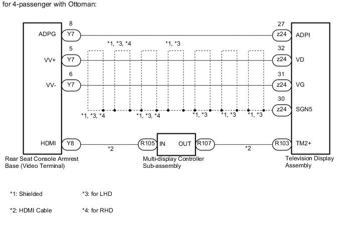
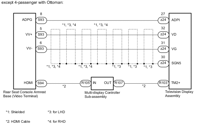
for Roof:
-
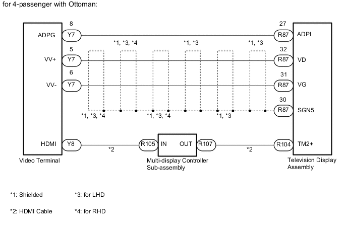
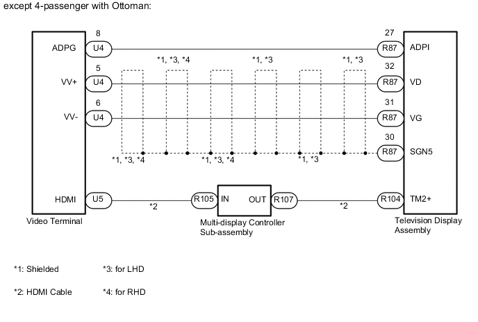
for Center Console Side:
PROCEDURE
-
CHECK HARNESS AND CONNECTOR (TELEVISION DISPLAY ASSEMBLY - VIDEO TERMINAL)
-
*1: for 4-passenger with Ottoman
-
*2: except 4-passenger with Ottoman
-
for Roof:
-
Disconnect the z24 television display assembly connector.
-
Disconnect the Y7*1 or S93*2 rear seat console armrest base (video terminal) connector.
-
Measure the resistance according to the value(s) in the table below.
Standard Resistance for 4-passenger with Ottoman Tester Connection Condition Specified Condition z24-32 (VD) - Y7-5 (VV+) Always Below 1 Ω z24-31 (VG) - Y7-6 (VV-) Always Below 1 Ω z24-27 (ADPI) - Y7-8 (ADPG) Always Below 1 Ω z24-32 (VD) or Y7-5 (VV+) - Body ground Always 10 kΩ or higher z24-31 (VG) or Y7-6 (VV-) - Body ground Always 10 kΩ or higher z24-27 (ADPI) or Y7-8 (ADPG) - Body ground Always 10 kΩ or higher z24-30 (SGN5) - Body ground Always 10 kΩ or higher except 4-passenger with Ottoman Tester Connection Condition Specified Condition z24-32 (VD) - S93-5 (VV+) Always Below 1 Ω z24-31 (VG) - S93-6 (VV-) Always Below 1 Ω z24-27 (ADPI) - S93-8 (ADPG) Always Below 1 Ω z24-32 (VD) or S93-5 (VV+) - Body ground Always 10 kΩ or higher z24-31 (VG) or S93-6 (VV-) - Body ground Always 10 kΩ or higher z24-27 (ADPI) or S93-8 (ADPG) - Body ground Always 10 kΩ or higher z24-30 (SGN5) - Body ground Always 10 kΩ or higher
-
-
for Center Console Side:
-
Disconnect the R87 television display assembly connector.
-
Disconnect the Y7*1 or U4*2 rear seat console armrest base (video terminal) connector.
-
Measure the resistance according to the value(s) in the table below.
Standard Resistance for 4-passenger with Ottoman Tester Connection Condition Specified Condition R87-32 (VD) - Y7-5 (VV+) Always Below 1 Ω R87-31 (VG) - Y7-6 (VV-) Always Below 1 Ω R87-27 (ADPI) - Y7-8 (ADPG) Always Below 1 Ω R87-32 (VD) or Y7-5 (VV+) - Body ground Always 10 kΩ or higher R87-31 (VG) or Y7-6 (VV-) - Body ground Always 10 kΩ or higher R87-27 (ADPI) or Y7-8 (ADPG) - Body ground Always 10 kΩ or higher R87-30 (SGN5) - Body ground Always 10 kΩ or higher except 4-passenger with Ottoman Tester Connection Condition Specified Condition R87-32 (VD) - U4-5 (VV+) Always Below 1 Ω R87-31 (VG) - U4-6 (VV-) Always Below 1 Ω R87-27 (ADPI) - U4-8 (ADPG) Always Below 1 Ω R87-32 (VD) or U4-5 (VV+) - Body ground Always 10 kΩ or higher R87-31 (VG) or U4-6 (VV-) - Body ground Always 10 kΩ or higher R87-27 (ADPI) or U4-8 (ADPG) - Body ground Always 10 kΩ or higher R87-30 (SGN5) - Body ground Always 10 kΩ or higher
-
NG 
REPAIR OR REPLACE HARNESS OR CONNECTOR
OK 
-
-
CHECK HARNESS AND CONNECTOR (HDMI CABLE)
-
Replace the harness and connector (HDMI cable) with a new or known good one.
-
Check if the same problem occurs again.
OK Same problem does not occur.
OK
END (HDMI CABLE IS DEFECTIVE)
NG
-
-
CHECK MULTI-DISPLAY CONTROLLER SUB-ASSEMBLY
-
Replace the multi-display controller sub-assembly with a new or known one Click here.
-
Check if the same problem occurs again.
OK Same problem does not occur.
OK
END (MULTI-DISPLAY CONTROLLER SUB-ASSEMBLY IS DEFECTIVE)
NG
PROCEED TO NEXT SUSPECTED AREA SHOWN IN PROBLEM SYMPTOMS TABLE Click here
-