AUDIO AND VISUAL SYSTEM, Diagnostic DTC:B157D
| DTC Code | DTC Name |
|---|---|
| B157D | DAB Tuner Antenna Disconnected |
DESCRIPTION
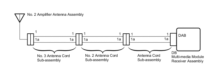
This DTC is stored when a malfunction occurs in the No. 2 amplifier antenna assembly which is connected to the multi-media module receiver assembly.
| DTC Code | DTC Detection Condition | Trouble Area |
|---|---|---|
| B157D | The No. 2 amplifier antenna assembly is not connected |
|
WIRING DIAGRAM
CAUTION / NOTICE / HINT
Note
-
Check that the antenna cable is properly installed and does not have any sharp bends, pinching or loose connections.
-
Depending on the parts that are replaced during vehicle inspection or maintenance, performing initialization, registration or calibration may be needed. Refer to Precaution for Navigation System.
PROCEDURE
-
CHECK CONNECTION OF DAB RADIO ANTENNA CABLE
-
Check if the DAB radio antenna cable is securely connected to the multi-media module receiver assembly.
OK DAB radio antenna cable is securely connected. Result Proceed to OK NG
NG 
SECURELY CONNECT DAB RADIO ANTENNA CABLE
OK 
-
-
CHECK VEHICLE TYPE
-
Check the vehicle type.
Model Model Proceed to w/o Telematics Transceiver A w/ Telematics Transceiver B
B 
CHECK ANTENNA CORD SUB-ASSEMBLY Click here
A
-
-
CHECK ANTENNA CORD SUB-ASSEMBLY
-
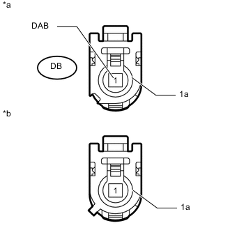
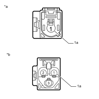
*a Front view of wire harness connector
(to Multi-media Module Receiver Assembly)
*b Front view of wire harness connector
(to No. 2 Antenna Cord Sub-assembly)
Remove the antenna connector from the multi-media module receiver assembly.
-
Remove the antenna connector from the No. 2 antenna cord sub-assembly.
-
Measure the resistance according to the value(s) in the table below.
Standard Resistance Tester Connection Condition Specified Condition DB-1 (DAB) - 1 Always Below 1 Ω DB-1a - 1a Always Below 1 Ω DB-1 (DAB) or 1 - Body ground Always 10 kΩ or higher DB-1a or 1a - Body ground Always 10 kΩ or higher Result Proceed to OK NG
NG
REPLACE ANTENNA CORD SUB-ASSEMBLY Click here
OK
-
-
CHECK NO. 2 ANTENNA CORD SUB-ASSEMBLY
-
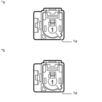
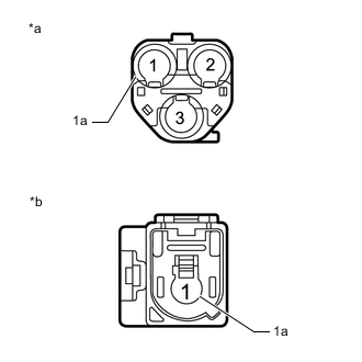
*a Front view of wire harness connector
(to Antenna Cord Sub-assembly)
*b Front view of wire harness connector
(to No. 3 Antenna Cord Sub-assembly)
Remove the antenna connector from the antenna cord sub-assembly.
-
Remove the antenna connector from the No. 3 antenna cord sub-assembly.
-
Measure the resistance according to the value(s) in the table below.
Standard Resistance Tester Connection Condition Specified Condition 1 - 1 Always Below 1 Ω 1a - 1a Always Below 1 Ω 1 or 1 - Body ground Always 10 kΩ or higher 1a or 1a - Body ground Always 10 kΩ or higher Result Proceed to OK NG
NG
REPLACE NO. 2 ANTENNA CORD SUB-ASSEMBLY Click here
OK
-
-
CHECK NO. 3 ANTENNA CORD SUB-ASSEMBLY
-
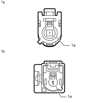
*a Front view of wire harness connector
(to No. 2 Antenna Cord Sub-assembly)
*b Front view of wire harness connector
(to No. 2 Amplifier Antenna Assembly)
Remove the antenna connector from the No. 2 antenna cord sub-assembly.
-
Remove the antenna connector from the No. 2 amplifier antenna assembly.
-
Measure the resistance according to the value(s) in the table below.
Standard Resistance Tester Connection Condition Specified Condition 1 - 1 Always Below 1 Ω 1a - 1a Always Below 1 Ω 1 or 1 - Body ground Always 10 kΩ or higher 1a or 1a - Body ground Always 10 kΩ or higher Result Proceed to OK NG
NG
REPLACE NO. 3 ANTENNA CORD SUB-ASSEMBLY Click here
OK
-
-
REPLACE NO. 2 AMPLIFIER ANTENNA ASSEMBLY
-
Replace the No. 2 amplifier antenna assembly with a new or known good one.
Result Proceed to NEXT
NEXT
-
-
CLEAR DTC
-
Clear the DTCs.
Result Proceed to NEXT
NEXT
-
-
CHECK FOR DTC
-
Recheck for DTCs and check if the same DTC is output again.
OK No DTCs are output. Result Proceed to OK NG
OK
END (NO. 2 AMPLIFIER ANTENNA ASSEMBLY IS DEFECTIVE)
NG
REPLACE MULTI-MEDIA MODULE RECEIVER ASSEMBLY Click here
-
-
CHECK ANTENNA CORD SUB-ASSEMBLY
-
*a Front view of wire harness connector
(to Multi-media Module Receiver Assembly)
*b Front view of wire harness connector
(to No. 2 Antenna Cord Sub-assembly)
Remove the antenna connector from the multi-media module receiver assembly.
-
Remove the antenna connector from the No. 2 antenna cord sub-assembly.
-
Measure the resistance according to the value(s) in the table below.
Standard Resistance Tester Connection Condition Specified Condition DB-1 (DAB) - 1 Always Below 1 Ω DB-1a - 1a Always Below 1 Ω DB-1 (DAB) or 1 - Body ground Always 10 kΩ or higher DB-1a or 1a - Body ground Always 10 kΩ or higher Result Proceed to OK NG
NG
REPLACE ANTENNA CORD SUB-ASSEMBLY Click here
OK
-
-
CHECK NO. 2 ANTENNA CORD SUB-ASSEMBLY
-
*a Front view of wire harness connector
(to Antenna Cord Sub-assembly)
*b Front view of wire harness connector
(to No. 3 Antenna Cord Sub-assembly)
Remove the antenna connector from the antenna cord sub-assembly.
-
Remove the antenna connector from the No. 3 antenna cord sub-assembly.
-
Measure the resistance according to the value(s) in the table below.
Standard Resistance Tester Connection Condition Specified Condition 1 - 1 Always Below 1 Ω 1a - 1a Always Below 1 Ω 1 or 1 - Body ground Always 10 kΩ or higher 1a or 1a - Body ground Always 10 kΩ or higher Result Proceed to OK NG
NG
REPLACE NO. 2 ANTENNA CORD SUB-ASSEMBLY Click here
OK
-
-
CHECK NO. 3 ANTENNA CORD SUB-ASSEMBLY
-
*a Front view of wire harness connector
(to No. 2 Antenna Cord Sub-assembly)
*b Front view of wire harness connector
(to No. 2 Amplifier Antenna Assembly)
Remove the antenna connector from the No. 2 antenna cord sub-assembly.
-
Remove the antenna connector from the No. 2 amplifier antenna assembly.
-
Measure the resistance according to the value(s) in the table below.
Standard Resistance Tester Connection Condition Specified Condition 1 - 1 Always Below 1 Ω 1a - 1a Always Below 1 Ω 1 or 1 - Body ground Always 10 kΩ or higher 1a or 1a - Body ground Always 10 kΩ or higher Result Proceed to OK NG
OK
GO TO STEP 6 Click here
NG
REPLACE NO. 3 ANTENNA CORD SUB-ASSEMBLY Click here
-