STEERING GEAR(for 2WD with VGRS) REASSEMBLY

CAUTION / NOTICE / HINT
Note
When installing, coat the parts indicated by arrows with silicon grease Click here.
PROCEDURE
-
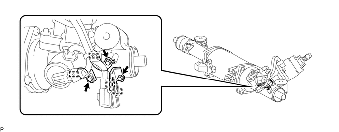
INSTALL STEERING ACTUATOR ASSEMBLY
-
Apply the supplied grease to the pinion of the steering actuator.
-
Apply grease to a new O-ring and install the O-ring to the steering actuator.
-
Install the spacer to the rack housing.
-
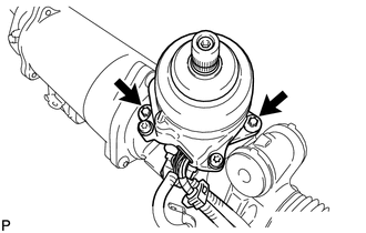
Using an "TORX" socket wrench, install the steering actuator with the 2 bolts.
- Torque:
- 15 N*m { 153 kgf*cm, 11 ft.*lbf }
Note
Make sure the O-ring is not pinched.
-
-
ADJUST PRELOAD
-
Clean and degrease the threaded areas of the rack guide spring cap and rack housing.
-
Apply FIPG material to the rack guide spring cap.
-
Using a m hexagon wrench, install the rack guide spring and rack guide spring cap to the rack housing.
Tech Tips
After fully tightening the rack guide spring cap, loosen it to align the matchmarks.
-
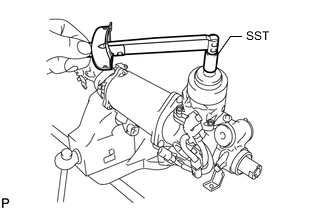
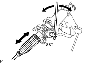
Using SST, rotate the pinion back and forth so that it turns properly, and then measure the preload (turning torque).
- SST
- 09616-00011
Tech Tips
-
Due to differences in the individual parts, the feeling of the steering handling may not be the same as it was before removal.
-
The preload should be within 0.3 N*m of the average value measured before removal.
Reference 0.9 to 2.1 N*m (10 to 21 kgf*cm, 8 to 18 in.*lbf) -
Clean and degrease the rack guide spring cap nut.
-
Apply FIPG material to the rack guide spring cap nut.
-
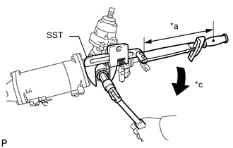
Text in Illustration *a Fulcrum Length *b Hold *c Turn Using SST, install the rack guide spring cap nut.
- SST
- 09922-10010
- Torque:
- without SST
- 69 N*m { 704 kgf*cm, 51 ft.*lbf }
- with SST
- 50 N*m { 510 kgf*cm, 37 ft.*lbf }
Tech Tips
-
Rotate SST in the direction shown in the illustration.
-
Use a torque wrench with a fulcrum length of 400 mm (15.7 in.).
-
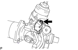
Install the harness cover with the bolt.
- Torque:
- 9.0 N*m { 92 kgf*cm, 80 in.*lbf }
-
-
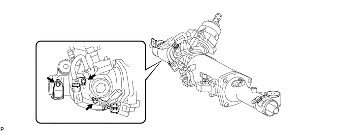
INSTALL HARNESS BRACKET
-
for LHD:
-
Install the 3 harness brackets with the 3 bolts.
- Torque:
- 9.0 N*m { 92 kgf*cm, 80 in.*lbf }
-
Attach the harness clamp to the harness bracket.
-
-
for RHD:
-
Install the 3 harness brackets with the 3 bolts.
- Torque:
- 9.0 N*m { 92 kgf*cm, 80 in.*lbf }
-
Attach the harness clamp to the harness bracket.
-
-
-
INSTALL STEERING RACK END SUB-ASSEMBLY
-
INSTALL NO. 1 STEERING RACK BOOT
-
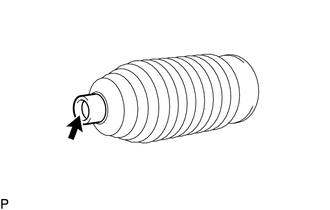
Apply silicon grease to the inside of the smaller diameter of the No. 1 steering rack boot.
-
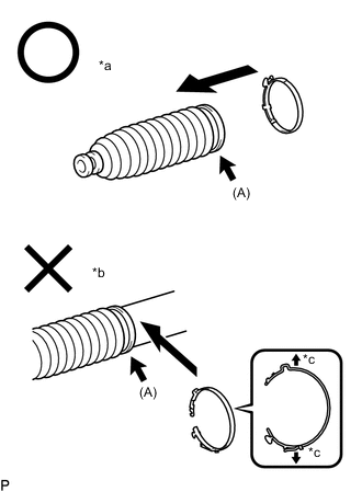
Text in Illustration *a Installing from side *b Installing perpendicularly *c Do not expand steering rack boot clamp for Type A:
-
Temporarily install a new No. 1 steering rack boot clamp to the larger diameter side of the No. 1 steering rack boot as shown by the arrow (A) in the illustration.
Note
-
Make sure to use a new No. 1 steering rack boot clamp.
-
Do not excessively expand the diameter of the No. 1 steering rack boot clamp when installing it.
-
Do not deform the No. 1 steering rack boot clamp.
-
If the diameter of the No. 1 steering rack boot clamp is expanded and then installed as shown in the illustration, the tightening torque will become uneven. As a result, rust may form due to water or other foreign matter entering between the boot and rack housing, causing a malfunction to occur.
-
Do not secure the boot with any objects other than the supply parts appropriate for the vehicle.
Tech Tips
Temporarily install a new No. 1 steering rack boot clamp, from which the claw has been removed, to the side of the No. 1 steering rack boot diameter.
-
-
Install the No. 1 steering rack boot to the groove on the rack housing.
Note
-
Do not twist the No. 1 steering rack boot when installing it.
-
Do not damage the No. 1 steering rack boot.
-
Check that there is no foreign matter or rust.
-
When the No. 1 steering rack boot is damaged, replace the No. 1 steering rack boot with a new one.
-
Do not install the No. 1 steering rack boot clamp after installing the No. 1 steering rack boot to the rack housing.
Tech Tips
Use the same procedure for the RH and LH sides.
-
-
-
for Type B:
Install the No. 1 steering rack boot to the groove on the rack housing.
Note
-
Do not twist the No. 1 steering rack boot when installing it.
-
Do not damage the No. 1 steering rack boot.
-
Check that there is no foreign matter or rust.
-
When the No. 1 steering rack boot is damaged, replace the No. 1 steering rack boot with a new one.
Tech Tips
Use the same procedure for the RH and LH sides.
-
-
-
INSTALL NO. 1 STEERING RACK BOOT CLAMP
-
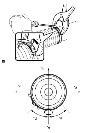
Text in Illustration *a Front of Vehicle *b Top of Vehicle *c Rear of Vehicle *d Clamp Protrusion Installation Range *e Bottom of Vehicle Type A:
Using pliers and a screwdriver, install the No. 1 steering rack boot clamp as shown in the illustration.
Note
-
Do not twist the No. 1 steering rack boot.
-
Do not damage the No. 1 steering rack boot.
Tech Tips
-
Install the No. 1 steering rack boot clamp protrusion within the range shown in the illustration.
-
Use the same procedure for the RH and LH sides.
-
-
Type B:
-
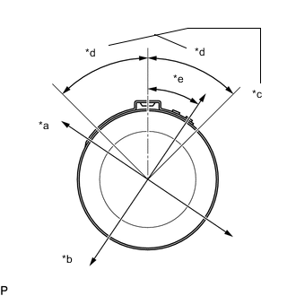
Install a new No. 1 steering rack boot clamp to the No. 1 steering rack boot.
Text in Illustration *a Top of Vehicle *b Front of Vehicle *c Staked Portion Within This Area *d 45° *e 34° Note
-
Do not twist the No. 1 steering rack boot.
-
Do not damage the No. 1 steering rack boot.
Tech Tips
Install the staked portion of the No. 1 steering rack boot clamp within the range shown in the illustration.
-
-
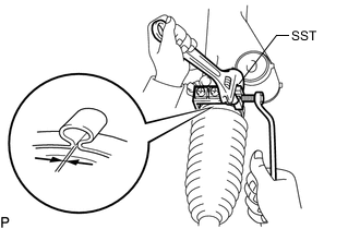
Press SST against the rack housing side, and stake the No. 1 steering rack boot clamp so that the clearance is the standard.
- SST
- 09521-24010
Note
-
Make sure that the No. 1 steering rack boot is not twisted.
-
Make sure that the No. 1 steering rack boot clamp is not staked too much.
-
-
Remove SST and measure the gap of the No. 1 steering rack boot clamp.
Standard 2.5 to 4.0 mm (0.0985 to 0.157 in.) Tech Tips
Use the same procedure for the RH and LH sides.
-
-
INSTALL STEERING RACK BOOT CLIP
-
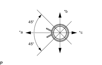
Text in Illustration *a Front of the vehicle *b Upward *c Rear of the vehicle Using pliers, install the 2 boot clips.
Tech Tips
Make sure that the each clip claw is positioned within the area shown in the illustration.
-
Using SST, turn the pinion and check that the rack boots expand and contract smoothly.
- SST
- 09616-00011
-
-
INSTALL TIE ROD ASSEMBLY LH
-
INSTALL TIE ROD ASSEMBLY RH
Tech Tips
Perform the same procedure as for the LH side.