POWER STEERING SYSTEM, Diagnostic DTC:C1552
| DTC Code | DTC Name |
|---|---|
| C1552 | PIG Power Supply Voltage Malfunction |
DESCRIPTION
The power steering converter assembly boosts the PIG power supply battery voltage from 12 V to approximately 46 V. This voltage is then supplied to the power steering ECU to operate the motors. As a fail-safe function, when the PIG power supply and power steering converter assembly are malfunctioning, power assistance stops.
| DTC No. | DTC Detection Condition | Trouble Area |
|---|---|---|
| C1552 | PIG power supply voltage malfunction |
|
WIRING DIAGRAM
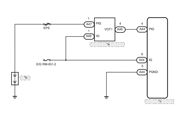
| *a | Power Steering Converter Assembly |
| *b | Battery |
| *c | Power Steering ECU |
PROCEDURE
-
CHECK CONNECTORS
-
Check the connection of the power steering ECU connector.
-
Visually inspect the terminals of the power steering ECU connector.
Result Result Proceed to Normal A Connectors not properly connected B Power steering ECU connector terminals abnormal C Note
If replacing the power steering ECU, initialize the rotation angle sensor value and calibrate the torque sensor zero point Click here.
B 
CONNECT CONNECTORS CORRECTLY
C
REPLACE POWER STEERING ECU Click here
A 
-
-
CHECK POWER STEERING ECU (PIG TERMINAL)
-
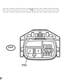
*1 Front view of wire harness connector: (to Power Steering ECU) Disconnect the A44 ECU connector.
-
Measure the voltage according to the value(s) in the table below.
Standard voltage Tester Connection Switch Condition Specified Condition A44-4 (PIG) - Body ground Engine switch on (IG) 30 to 48 V Note
If replacing the power steering ECU, initialize the rotation angle sensor value and calibrate the torque sensor zero point Click here.
OK
REPLACE POWER STEERING ECU Click here
NG
-
-
CHECK HARNESS AND CONNECTOR (CONVERTER - BATTERY AND ECU)
-
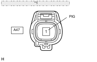
*1 Front view of wire harness connector: (to Power Steering Converter Assembly) Disconnect the A47 converter connector.
-
Measure the voltage according to the value(s) in the table below.
Standard voltage Tester Connection Switch Condition Specified Condition A47-1 (PIG) - Body ground Engine switch on (IG) 11 to 14 V -
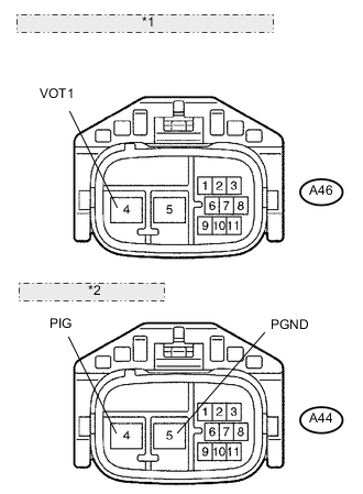
*1 Front view of wire harness connector: (to Power Steering Converter Assembly) *2 (to Power Steering ECU) Disconnect the A44 ECU connector.
-
Disconnect the A46 converter connector.
-
Measure the resistance according to the value(s) in the table below.
Standard resistance Tester Connection Condition Specified Condition A44-4 (PIG) - A46-4 (VOT1) Always Below 1 Ω A44-5 (PGND) - Body ground Always Below 1 Ω A44-4 (PIG) - Body ground Always 10 kΩ or higher
NG
REPAIR OR REPLACE HARNESS OR CONNECTOR
OK
-
-
CHECK HARNESS AND CONNECTOR (CONVERTER - BATTERY)
-
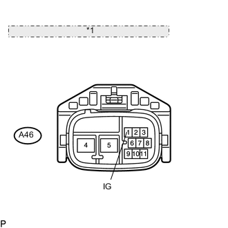
*1 Front view of wire harness connector: (to Power Steering Converter Assembly) Disconnect the A46 converter connector.
-
Measure the voltage according to the value(s) in the table below.
Standard voltage Tester Connection Switch Condition Specified Condition A46-1 (IG) - Body ground Engine switch on (IG) 11 to 14 V
OK
REPLACE POWER STEERING CONVERTER ASSEMBLY Click here
NG
REPAIR OR REPLACE HARNESS OR CONNECTOR
-