STEERING GEAR(w/o VGRS) REASSEMBLY

CAUTION / NOTICE / HINT
Note
When installing, coat the parts indicated by arrows with silicon grease Click here.
PROCEDURE
-
INSTALL STEERING RACK END SUB-ASSEMBLY
-
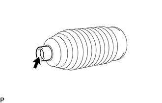
Install 2 new claw washers.
Tech Tips
Align the claws of the claw washer with the steering rack grooves.
-
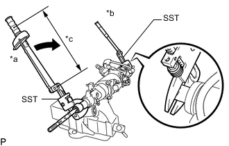
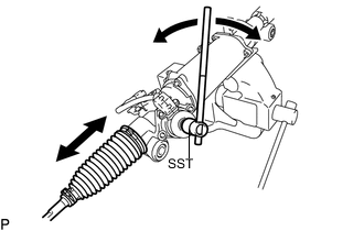
Text in Illustration *a Fulcrum Length *b Hold *c Turn Using 2 SST, install the steering rack end sub-assembly (RH side).
- SST
- 09922-10010
- Torque:
- Without SST
- 145 N*m { 1479 kgf*cm, 107 ft.*lbf }
- With SST
- 110 N*m { 1122 kgf*cm, 81 ft.*lbf }
Note
-
Use a torque wrench with a fulcrum length of 345 mm (1.13 ft.).
-
This torque value is effective when SST is parallel to the torque wrench.
Tech Tips
Using SST, hold the steering rack and install the steering rack end sub-assembly.
-
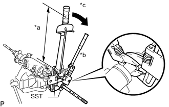
Text in Illustration *a Fulcrum Length *b Hold *c Turn Using 2 SST, install the steering rack end sub-assembly (LH side).
- SST
- 09922-10010
- Torque:
- Without SST
- 145 N*m { 1479 kgf*cm, 107 ft.*lbf }
- With SST
- 110 N*m { 1122 kgf*cm, 81 ft.*lbf }
Note
-
Use a torque wrench with a fulcrum length of 345 mm (1.13 ft.).
-
This torque value is effective when SST is parallel to the torque wrench.
Tech Tips
Using SST, hold the steering rack and install the steering rack end sub-assembly.
-
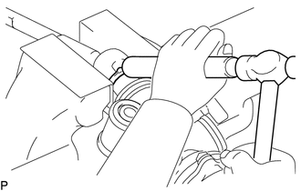
Using a brass bar and a hammer, stake the 2 claw washers.
Note
Avoid any impact to the steering rack.
-
-
INSTALL NO.1 STEERING RACK BOOT
-
Apply silicon grease to the inside of the smaller diameter of the No. 1 steering rack boot.
-
for Type A:
-
Text in Illustration *a Installing from side *b Installing perpendicularly *c Do not expand steering rack boot clamp Temporarily install a new No. 1 steering rack boot clamp to the larger diameter side of the No. 1 steering rack boot as shown by the arrow (A) in the illustration.
Note
-
Make sure to use a new No. 1 steering rack boot clamp.
-
Do not excessively expand the diameter of the No. 1 steering rack boot clamp when installing it.
-
Do not deform the No. 1 steering rack boot clamp.
-
If the diameter of the No. 1 steering rack boot clamp is expanded and then installed as shown in the illustration, the tightening torque will become uneven. As a result, rust may form due to water or other foreign matter entering between the boot and rack housing, causing a malfunction to occur.
-
Do not secure the boot with any objects other than the supply parts appropriate for the vehicle.
Tech Tips
Temporarily install a new No. 1 steering rack boot clamp, from which the claw has been removed, to the side of the No. 1 steering rack boot diameter.
-
-
Install the No. 1 steering rack boot to the groove on the rack housing.
Note
-
Do not twist the No. 1 steering rack boot when installing it.
-
Do not damage the No. 1 steering rack boot.
-
Check that there is no foreign matter or rust.
-
When the No. 1 steering rack boot is damaged, replace the No. 1 steering rack boot with a new one.
-
Do not install the No. 1 steering rack boot clamp after installing the No. 1 steering rack boot to the rack housing.
Tech Tips
Use the same procedure for the RH and LH sides.
-
-
-
for Type B:
Install the No. 1 steering rack boot to the groove on the rack housing.
Note
-
Do not twist the No. 1 steering rack boot when installing it.
-
Do not damage the No. 1 steering rack boot.
-
Check that there is no foreign matter or rust.
-
When the No. 1 steering rack boot is damaged, replace the No. 1 steering rack boot with a new one.
Tech Tips
Use the same procedure for the RH and LH sides.
-
-
-
INSTALL NO.1 STEERING RACK BOOT CLAMP
-
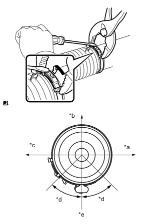
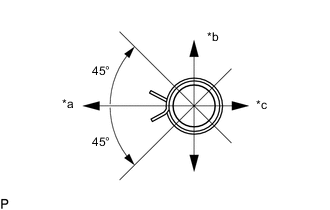
Text in Illustration *a Front of Vehicle *b Top of Vehicle *c Rear of Vehicle *d Clamp Protrusion Installation Range *e Bottom of Vehicle Type A:
Using pliers and a screwdriver, install the No. 1 steering rack boot clamp as shown in the illustration.
Note
-
Do not twist the No. 1 steering rack boot.
-
Do not damage the No. 1 steering rack boot.
Tech Tips
-
Install the No. 1 steering rack boot clamp protrusion within the range shown in the illustration.
-
Use the same procedure for the RH and LH sides.
-
-
Type B:
-
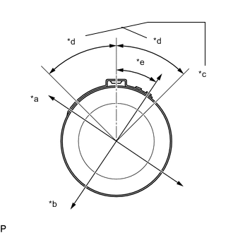
Text in Illustration *a Top of Vehicle *b Front of Vehicle *c Staked Portion Within This Area *d 45° *e 34° Install a new No. 1 steering rack boot clamp to the No. 1 steering rack boot.
Note
-
Do not twist the No. 1 steering rack boot.
-
Do not damage the No. 1 steering rack boot.
Tech Tips
Install the staked portion of the No. 1 steering rack boot clamp within the range shown in the illustration.
-
-
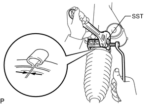
Press SST against the rack housing side, and stake the No. 1 steering rack boot clamp so that the clearance is the standard.
- SST
- 09521-24010
Note
-
Make sure that the No. 1 steering rack boot is not twisted.
-
Make sure that the No. 1 steering rack boot clamp is not staked too much.
-
-
Remove SST and measure the gap of the No. 1 steering rack boot clamp.
Standard 2.5 to 4.0 mm (0.0985 to 0.157 in.) Tech Tips
Use the same procedure for the RH and LH sides.
-
-
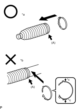
INSTALL STEERING RACK BOOT CLIP
-
Text in Illustration *a Front of the vehicle *b Upward *c Rear of the vehicle Using pliers, install the 2 boot clips.
Tech Tips
Make sure that the each clip claw is positioned within the area shown in the illustration.
-
Using SST, turn the pinion and check that the rack boots expand and contract smoothly.
- SST
- 09616-00011
-
-
INSTALL TIE ROD ASSEMBLY LH
-
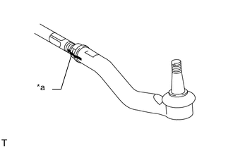
Text in Illustration *a Matchmark Install the lock nut and the tie rod assembly to the rack end until the matchmarks are aligned.
Tech Tips
After adjusting toe-in, torque the lock nut.
-
-
INSTALL TIE ROD ASSEMBLY RH
Tech Tips
Perform the same procedure as for the LH side.