POWER STEERING SYSTEM, Diagnostic DTC:C1515, C1516, C1525, C1526
| DTC Code | DTC Name |
|---|---|
| C1515 | Torque Sensor Zero Point Adjustment Undone |
| C1516 | Torque Sensor Zero Point Adjustment Incomplete |
| C1525 | Rotation Angle Sensor Initialization Undone |
| C1526 | Rotation Angle Sensor Initialization Incomplete |
DESCRIPTION
-
These DTCs do not indicate a malfunction. The power steering ECU stores these DTCs (C1515 or C1525) when it determines that motor rotation angle sensor value initialization and torque sensor zero point calibration have not been performed. When the IG terminal voltage is 9 V or less, motor rotation angle sensor initialization and torque sensor zero point calibration cannot be performed.
-
These DTCs do not indicate a malfunction. The power steering ECU stores these DTCs (C1516 or C1526) when it determines that motor rotation angle sensor value initialization and torque sensor zero point calibration are incomplete.
| DTC No. | DTC Detection Condition | Procedure |
|---|---|---|
| C1515 | This DTC is detected when torque sensor zero point calibration has not been performed. | There is no malfunction if this DTC is not output again after performing zero point calibration. |
| C1516 | Steering zero point calibration is incomplete due to the steering wheel being touched during calibration. | There is no malfunction if this DTC is not output again after clearing the DTCs and torque sensor calibration value, and performing zero point calibration. |
| C1525 | This DTC is detected when rotation angle sensor value initialization has not been performed. | There is no malfunction if this DTC is not output again after performing rotation angle sensor value initialization. |
| C1526 | Rotation angle sensor value initialization is incomplete due to the steering wheel being touched during calibration. | There is no malfunction if this DTC is not output again after clearing the DTCs and torque sensor calibration value, and performing rotation angle sensor value initialization. |
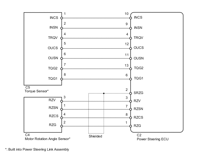
WIRING DIAGRAM
PROCEDURE
-
RECONFIRM DTC
-
Check for DTCs (see page ). If DTCs C1515 and C1526 are output, clear the DTCs Click here.
NEXT 
-
-
INITIALIZE ROTATION ANGLE SENSOR AND CALIBRATE TORQUE SENSOR ZERO POINT
-
Initialize the rotation angle sensor value and calibrate the torque sensor zero point Click here.
NEXT
-
-
RECONFIRM DTC
-
Check for DTCs Click here.
Result Result Proceed to DTCs are still output after performing rotation angle sensor value initialization and steering zero point calibration 3 times. A DTCs are still output after performing rotation angle sensor value initialization and steering zero point calibration once or twice. B DTC is not output. C Tech Tips
Replace the power steering ECU if DTCs are still output after performing rotation angle sensor value initialization and steering zero point calibration 3 times.
B 
INITIALIZE ROTATION ANGLE SENSOR AND CALIBRATE TORQUE SENSOR ZERO POINT Click here
C
END
A
-
-
CHECK CONNECTORS
-
Check the connection of the power steering ECU and power steering link assembly connectors.
-
Visually inspect the terminals of the power steering ECU and power steering link assembly connectors.
Result Result Proceed to Normal A Connectors not properly connected B Power steering ECU connector terminals abnormal C Power steering link assembly connector terminals abnormal (w/ VGRS) D Power steering link assembly connector terminals abnormal (w/o VGRS) E Note
-
If replacing the power steering link assembly, clear the rotation angle sensor value calibration value, initialize the rotation angle sensor value, and calibrate the torque sensor zero point Click here.
-
If replacing the power steering ECU, initialize the rotation angle sensor value and calibrate the torque sensor zero point Click here.
-
B
CONNECT CONNECTORS CORRECTLY
C
REPLACE POWER STEERING ECU Click here
D
REPLACE POWER STEERING LINK ASSEMBLY (w/ VGRS) Click here
E
REPLACE POWER STEERING LINK ASSEMBLY (w/o VGRS) Click here
A
-
-
CHECK HARNESS AND CONNECTOR (POWER STEERING ECU - POWER STEERING LINK ASSEMBLY)
-
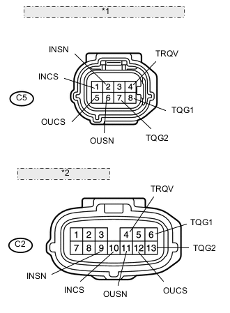
*1 Front view of wire harness connector: (to Torque Sensor) *2 (to Power Steering ECU) Disconnect the C2 ECU connector.
-
Disconnect the C5 sensor connector.
-
Measure the resistance according to the value(s) in the table below.
Standard resistance Tester Connection Condition Specified Condition C5-1 (INCS) - C2-10 (INCS) Always Below 1 Ω C5-2 (INSN) - C2-9 (INSN) Always Below 1 Ω C5-4 (TRQV) - C2-4 (TRQV) Always Below 1 Ω C5-5 (OUCS) - C2-12 (OUCS) Always Below 1 Ω C5-6 (OUSN) - C2-11 (OUSN) Always Below 1 Ω C5-7 (TQG2) - C2-13 (TQG2) Always Below 1 Ω C5-8 (TQG1) - C2-6 (TQG1) Always Below 1 Ω C5-1 (INCS) - Body ground Always 10 kΩ or higher C5-2 (INSN) - Body ground Always 10 kΩ or higher C5-4 (TRQV) - Body ground Always 10 kΩ or higher C5-5 (OUCS) - Body ground Always 10 kΩ or higher C5-6 (OUSN) - Body ground Always 10 kΩ or higher C5-7 (TQG2) - Body ground Always 10 kΩ or higher C5-8 (TQG1) - Body ground Always 10 kΩ or higher -
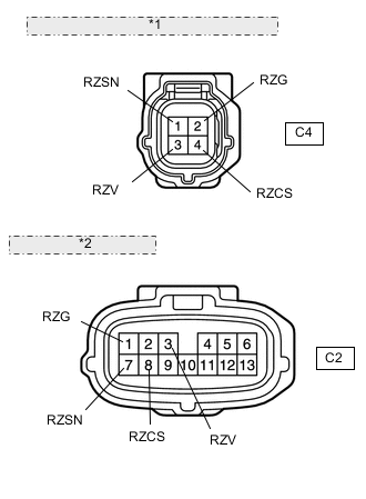
*1 Front view of wire harness connector: (to Motor Rotation Angle Sensor) *2 (to Power Steering ECU) Disconnect the C4 sensor connector.
-
Measure the resistance according to the value(s) in the table below.
Standard resistance Tester Connection Condition Specified Condition C4-1 (RZSN) - C2-7 (RZSN) Always Below 1 Ω C4-2 (RZG) - C2-1 (RZG) Always Below 1 Ω C4-3 (RZV) - C2-3 (RZV) Always Below 1 Ω C4-4 (RZCS) - C2-8 (RZCS) Always Below 1 Ω C4-1 (RZSN) - Body ground Always 10 kΩ or higher C4-2 (RZG) - Body ground Always 10 kΩ or higher C4-3 (RZV) - Body ground Always 10 kΩ or higher C4-4 (RZCS) - Body ground Always 10 kΩ or higher
NG
REPAIR OR REPLACE HARNESS OR CONNECTOR
OK
-
-
INSPECT POWER STEERING LINK ASSEMBLY (TORQUE SENSOR AND MOTOR ROTATION ANGLE SENSOR)
-
Disconnect the C5 torque sensor connector.
-
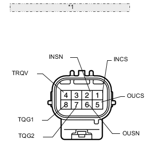
*1 Component without harness connected: (Torque Sensor) Measure the resistance according to the value(s) in the table below.
Standard resistance Tester Connection Condition Specified Condition 1 (INCS) - 7 (TQG2) Always 90 to 170 Ω 2 (INSN) - 7 (TQG2) Always 300 to 430 Ω 4 (TRQV) - 8 (TQG1) Always 4 to 14 Ω 5 (OUCS) - 7 (TQG2) Always 90 to 170 Ω 6 (OUSN) - 7 (TQG2) Always 300 to 430 Ω -
Disconnect the C4 motor rotation angle sensor connector.
-
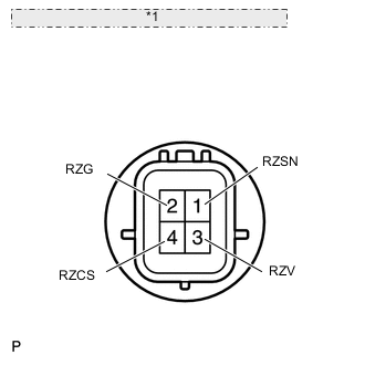
*1 Component without harness connected: (Motor Rotation Angle Sensor) Measure the resistance according to the value(s) in the table below.
Standard resistance Tester Connection Condition Specified Condition 1 (RZSN) - 2 (RZG) Always 50 to 140 Ω 3 (RZV) - 2 (RZG) Always 15 to 45 Ω 4 (RZCS) - 2 (RZG) Always 50 to 140 Ω Result Result Proceed to OK A NG (w/ VGRS) B NG (w/o VGRS) C Note
-
If replacing the power steering link assembly, clear the rotation angle sensor value calibration value, initialize the rotation angle sensor value, and calibrate the torque sensor zero point Click here.
-
If replacing the power steering ECU, initialize the rotation angle sensor value and calibrate the torque sensor zero point Click here.
-
A
REPLACE POWER STEERING ECU Click here
B
REPLACE POWER STEERING LINK ASSEMBLY (w/ VGRS) Click here
C
REPLACE POWER STEERING LINK ASSEMBLY (w/o VGRS) Click here
-