STEERING LOCK SYSTEM Unable to Unlock Steering Wheel
DESCRIPTION
The main body ECU supplies the power to activate the motor of the steering lock actuator assembly.
The steering lock actuator activates the steering lock motor and moves the lock bar into the steering column to lock the steering wheel.
The steering lock may not release when the lock bar gets stuck in the lock hole of the steering column. In this case, if an engine start operation is performed while shaking the steering wheel in the same manner as is done for a vehicle with a mechanical key, the lock bar will release.
The diagnosis information of the steering lock ECU is transmitted to the intelligent tester via the certification ECU as the steering lock ECU is not connected to the CAN communication system.
WIRING DIAGRAM
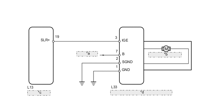
| *a | from Battery |
| *b | Steering Lock Motor |
| *c | Main Body ECU |
| *d | Steering Lock Actuator Assembly (Steering Lock ECU) |
CAUTION / NOTICE / HINT
Tech Tips
When the engine switch is off, the main body ECU may occasionally go into a non-active state called sleep mode. Therefore, before proceeding with the inspection, it is necessary to perform the following steps to wake up the ECU:
With the engine switch off, open the driver door. Then (with the engine switch still off) open and close any door several times at 1.5 second intervals.
PROCEDURE
-
CHECK ENGINE SWITCH
-
Check the power source mode change.
-
When the key is inside the vehicle and the shift lever is in P, check that pressing the engine switch causes the power source mode to change as follows:
OK off → on(ACC) → on(IG) → off Result Result Proceed to OK A NG (for 1UR-FE) B NG (for 1UR-FSE) C
-
B 
GO TO ENTRY AND START SYSTEM (POWER SOURCE MODE DOES NOT CHANGE) Click here
C
GO TO ENTRY AND START SYSTEM (POWER SOURCE MODE DOES NOT CHANGE) Click here
A 
-
-
CHECK FOR DTC (MAIN BODY ECU)
-
Check the DTCs of the main body ECU by following the prompts displayed on the intelligent tester screen (See page for 1UR-FE: , for 1UR-FSE: Click here).
OK No DTCs related to main body ECU are output. Result Result Proceed to OK A NG (for 1UR-FE) B NG (for 1UR-FSE) C
B
GO TO RELEVANT DTC Click here
C
GO TO RELEVANT DTC Click here
A
-
-
CHECK FOR DTC (CERTIFICATION ECU)
-
Check the DTCs of the certification ECU by following the prompts displayed on the intelligent tester screen Click here.
OK No DTCs related to certification ECU are output.
NG
GO TO RELEVANT DTC Click here
OK
-
-
READ VALUE USING INTELLIGENT TESTER (LOCK/UNLOCK RECEIVE)
-
Within 10 seconds of the engine switch being turned on (IG), check the Data List and read the value displayed on the intelligent tester screen.
Entry & Start Tester Display Measurement Item/Range Normal Condition Diagnostic Note Lock / Unlock Receive Steering lock command reception record/ YES or NO YES: Steering lock / unlock signal received
NO: Steering lock / unlock signal not received
- OK YES is displayed on the intelligent tester screen.
NG 
READ VALUE USING INTELLIGENT TESTER (S CODE CHECK) Click here
OK
-
-
CHECK HARNESS AND CONNECTOR (STEERING LOCK ECU - BODY GROUND)
-
Disconnect the L33 steering lock ECU connector.
-
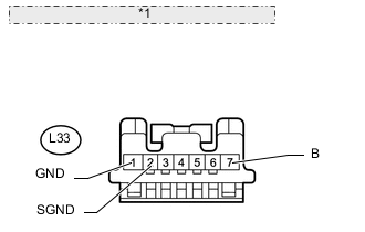
*1 Front view of wire harness connector: (to Steering Lock Actuator) Measure the resistance and voltage according to the value(s) in the table below.
Standard Voltage Tester Connection Condition Specified Condition L33-7 (B) - L33-1 (GND) Always 11 to 14 V L33-7 (B) - L33-2 (SGND) Always 11 to 14 V Standard Resistance Tester Connection Condition Specified Condition L33-1 (GND) - Body ground Always Below 1 Ω L33-2 (SGND) - Body ground Always Below 1 Ω
NG
REPAIR OR REPLACE HARNESS OR CONNECTOR
OK
-
-
CHECK STEERING LOCK ECU
-
Move the shift lever to P.
-
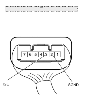
*1 Component with harness connected: (Steering Lock Actuator) Immediately after turning the engine switch on (IG), inspect the voltage between terminals 3 (IGE) and 2 (SGND) of the steering lock ECU.
Result Result Proceed to Measurement is 11 to 14 V, and measurement never becomes 1 V or less A Immediately after turning engine switch on (IG), measurement is 1 V or less (w/o VGRS) B Immediately after turning engine switch on (IG), measurement is 1 V or less (for 2WD with VGRS) C Immediately after turning engine switch on (IG), measurement is 1 V or less (for AWD with VGRS) D
A
REPAIR OR REPLACE HARNESS OR CONNECTOR
B
REPLACE STEERING LOCK ACTUATOR ASSEMBLY (STEERING LOCK ECU) Click here
C
REPLACE STEERING LOCK ACTUATOR ASSEMBLY (STEERING LOCK ECU) Click here
D
REPLACE STEERING LOCK ACTUATOR ASSEMBLY (STEERING LOCK ECU) Click here
-
-
READ VALUE USING INTELLIGENT TESTER (S CODE CHECK)
-
Use the Data List to check if the S code certification is functioning properly.
Entry & Start Tester Display Measurement Item/Range Normal Condition Diagnostic Note S Code Check S code match record/ NG or OK NG: S code not matched
OK: S code matched
- OK OK is displayed on the intelligent tester.
NG
REPLACE ID CODE BOX Click here
OK
-
-
READ VALUE USING INTELLIGENT TESTER (L CODE CHECK)
-
Use the Data List to check if the L code certification is functioning properly.
Entry & Start Tester Display Measurement Item/Range Normal Condition Diagnostic Note L Code Check L code match record/ NG or OK NG: L code not matched
OK: L code matched
- OK OK is displayed on the intelligent tester.
NG
REPLACE ID CODE BOX Click here
OK
-
-
REPLACE STEERING LOCK ACTUATOR ASSEMBLY (STEERING LOCK ECU)
-
Replace the steering lock actuator assembly (steering lock ECU) (See page w/o VGRS: , for 2WD with VGRS: , for AWD with VGRS: Click here).
NEXT
-
-
CHECK STEERING LOCK RELEASE OPERATION
-
Turn the engine switch on (IG).
-
Operate the steering wheel and check the steering lock condition.
OK Steering lock is released.
OK
END (STEERING LOCK ECU IS DEFECTIVE)
NG
REPLACE CERTIFICATION ECU
-
-
REPLACE ID CODE BOX
-
Replace the ID code box.
NEXT
-
-
READ VALUE USING INTELLIGENT TESTER (S CODE CHECK)
-
Use the Data List to check if the S code certification is functioning properly.
Entry & Start Tester Display Measurement Item/Range Normal Condition Diagnostic Note S Code Check S code match record/ NG or OK NG: S code not matched
OK: S code matched
- OK OK is displayed on the intelligent tester.
OK
END (ID CODE BOX IS DEFECTIVE)
NG
REPLACE CERTIFICATION ECU
-
-
REPLACE ID CODE BOX
-
Replace the ID code box.
NEXT
-
-
READ VALUE USING INTELLIGENT TESTER (L CODE CHECK)
-
Use the Data List to check if the L code certification is functioning properly.
Entry & Start Tester Display Measurement Item/Range Normal Condition Diagnostic Note L Code Check L code match record/ NG or OK NG: L code not matched
OK: L code matched
- OK OK is displayed on the intelligent tester. Result Result Proceed to OK A NG (w/o VGRS) B NG (for 2WD with VGRS) C NG (for AWD with VGRS) D
A
END (ID CODE BOX IS DEFECTIVE)
B
REPLACE STEERING LOCK ACTUATOR ASSEMBLY (STEERING LOCK ECU) Click here
C
REPLACE STEERING LOCK ACTUATOR ASSEMBLY (STEERING LOCK ECU) Click here
D
REPLACE STEERING LOCK ACTUATOR ASSEMBLY (STEERING LOCK ECU) Click here
-