STEERING LOCK SYSTEM, Diagnostic DTC:B2782
| DTC Code | DTC Name |
|---|---|
| B2782 | Power Source Control ECU Malfunction |
DESCRIPTION
The steering lock ECU activates the steering lock motor by the power from the main body ECU through the IGE circuit. This prevents the steering from being locked while the vehicle is moving.
The diagnosis information of the steering lock ECU is transmitted to the tester via the certification ECU as the steering lock ECU is not connected to the CAN communication system.
| DTC Code | Detection Condition | Trouble Area |
|---|---|---|
| B2782 | IGE power supply circuit malfunction |
|
WIRING DIAGRAM
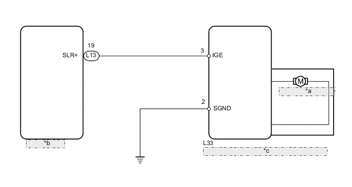
| *a | Steering Lock Motor |
| *b | Main Body ECU |
| *c | Steering Lock Actuator (Steering Lock ECU) |
CAUTION / NOTICE / HINT
Tech Tips
When the engine switch is off, the main body ECU may occasionally go into a non-active state called sleep mode. Therefore, before proceeding with the inspection, it is necessary to perform the following step to wake up the ECU:
With the engine switch off, open the driver door. Then (with the engine switch still off) open and close any door several times at 1.5 second intervals.
PROCEDURE
-
CHECK DTC (CERTIFICATION ECU)
-
Connect the intelligent tester to the DLC3.
-
Turn the engine switch on (IG) and press the intelligent tester main switch ON.
-
Read the DTCs of the certification ECU by following the prompts displayed on the intelligent tester.
OK DTC B2782 is output, but DTC B2785 (LIN bus line malfunction) is not output.
NG 
GO TO DTC CHART (B2785) Click here
OK 
-
-
CHECK STEERING LOCK ACTUATOR (IGE VOLTAGE)
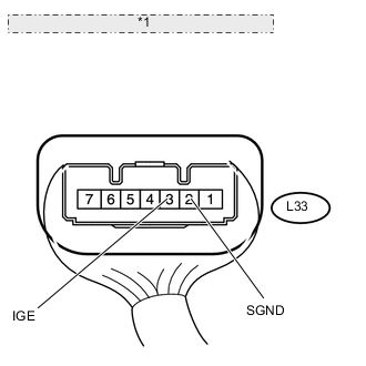
*1 Component with harness connected: (Steering Lock Actuator)
-
Measure the voltage according to the value(s) in the table below.
Standard voltage Tester Connection Switch Condition Specified Condition L33-3 (IGE) - L33-2 (SGND) Engine switch on (IG)
(When steering lock motor is operating)
Below 1 V Engine switch on (IG)
(When steering lock motor is not operating)
11 to 14 V Tech Tips
When the steering lock is activated and the engine switch is turned on (IG), the steering lock motor activates to release the steering lock. The motor operation occurs for 2 to 15 seconds.
OK
REPLACE STEERING LOCK ACTUATOR
NG
-
-
CHECK HARNESS AND CONNECTOR (STEERING LOCK ACTUATOR - BODY GROUND)
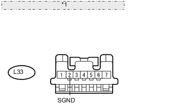
*1 Front view of wire harness connector: (to Steering Lock Actuator)
-
Disconnect the L33 steering lock actuator connector.
-
Measure the resistance according to the value(s) in the table below.
Standard resistance Tester Connection Condition Specified Condition L33-2 (SGND) - Body ground Always Below 1 Ω
NG
REPAIR OR REPLACE HARNESS OR CONNECTOR
OK
-
-
CHECK HARNESS AND CONNECTOR (STEERING LOCK ACTUATOR - MAIN BODY ECU)
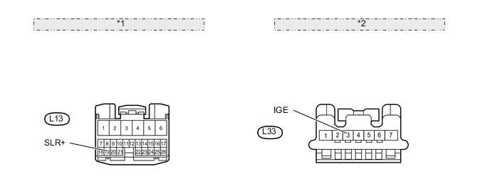
*1 Front view of wire harness connector: (to Main Body ECU) *2 Front view of wire harness connector: (to Steering Lock ECU)
-
Disconnect the L13 main body ECU connector.
-
Disconnect the L33 steering lock actuator connector.
-
Measure the resistance according to the value(s) in the table below.
Standard resistance Tester Connection Condition Specified Condition L33-3 (IGE) - L13-19 (SLR+) Always Below 1 Ω L33-3 (IGE) or L13-19 (SLR+) - Body ground Always 10 kΩ or higher
OK
REPLACE MAIN BODY ECU
NG
REPAIR OR REPLACE HARNESS OR CONNECTOR
-