POWER TILT AND POWER TELESCOPIC STEERING COLUMN SYSTEM IG Power Source Circuit
DESCRIPTION
When the engine switch is turned on (IG), the IG power source circuit supplies positive (+) voltage to the multiplex tilt and telescopic ECU.
The multiplex tilt and telescopic ECU also receives engine switch signals via this circuit.
WIRING DIAGRAM
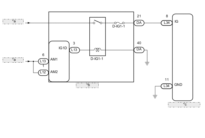
| *a | from Battery |
| *b | Main Body ECU |
| *c | Multiplex Tilt and Telescopic ECU |
PROCEDURE
-
INSPECT FUSE (D-IG1-1)
-
Remove the D-IG1-1 fuse from the main body ECU.
-
Measure the resistance of the fuse.
Standard resistance Tester Connection Condition Specified Condition D-IG1-1 fuse Always Below 1 Ω
NG 
REPLACE FUSE
OK 
-
-
CHECK MULTIPLEX TILT AND TELESCOPIC ECU (IG TERMINAL VOLTAGE)
-
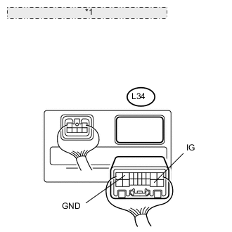
*1 Rear view of wire harness connector: (to Multiplex Tilt and Telescopic ECU) Disconnect the L34 connector from the multiplex tilt and telescopic ECU.
-
Measure the voltage according to the value(s) in the table below.
Standard voltage Tester Connection Switch Condition Specified Condition L34-8 (IG) - L34-11 (GND) Engine switch on (IG) 11 to 14 V
OK
PROCEED TO NEXT CIRCUIT INSPECTION SHOWN IN PROBLEM SYMPTOMS TABLE Click here
NG
-
-
CHECK HARNESS AND CONNECTOR (MULTIPLEX TILT AND TELESCOPIC ECU - BODY GROUND)
-
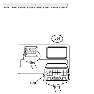
*1 Rear view of wire harness connector: (to Multiplex Tilt and Telescopic ECU) Measure the resistance according to the value(s) in the table below.
Standard resistance Tester Connection Condition Specified Condition L34-11 (GND) - Body ground Always Below 1 Ω
NG
REPAIR OR REPLACE HARNESS OR CONNECTOR
OK
-
-
CHECK HARNESS AND CONNECTOR (MULTIPLEX TILT AND TELESCOPIC ECU - MAIN BODY ECU)
-
Measure the voltage according to the value(s) in the table below.
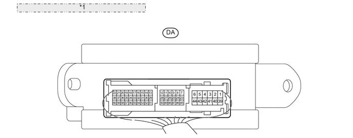
*1 Component with harness connected: (Main Body ECU) Standard voltage Tester Connection Switch Condition Specified Condition DA-21 - Body ground Engine switch on (IG) 11 to 14 V
OK
REPAIR OR REPLACE HARNESS OR CONNECTOR (MULTIPLEX TILT AND TELESCOPIC ECU - MAIN BODY ECU)
NG
REPAIR OR REPLACE HARNESS OR CONNECTOR (MAIN BODY ECU - BATTERY)
-