ELECTRIC PARKING BRAKE SYSTEM Electric Parking Brake System AUTO Function Circuit
DESCRIPTION
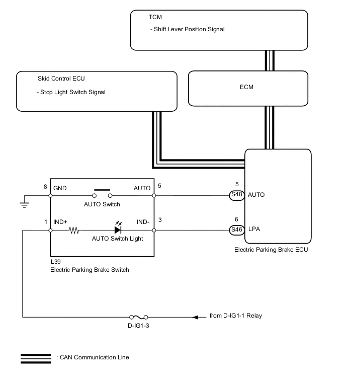
The electric parking brake ECU receives shift position information from the TCM through CAN communication. When the engine switch is on (IG) and the electric parking brake switch AUTO switch is turned ON, the electric parking brake system AUTO function operates as follows: 1) when the brake pedal is depressed and the shift lever is moved from P to a position other than P, parking brake release control automatically operates; or 2) when the brake pedal is depressed and the shift lever is moved from a position other than P to P, parking brake lock control automatically operates.
WIRING DIAGRAM
CAUTION / NOTICE / HINT
Note
-
If the electric parking brake ECU or parking brake with bracket actuator assembly is replaced, perform the "Reset Memory" and "ACQUIRE TENSION SENSOR ZERO POINT" procedures Click here.
-
Before disconnecting connectors or fuses, turn the engine switch off and wait 20 seconds or more.
PROCEDURE
-
CHECK AUTO SWITCH (DATA LIST)
-
Turn the engine switch off.
-
Connect the intelligent tester to the DLC3.
-
Turn the engine switch on (IG) and the tester ON.
-
Enter the following menus:
Select: Chassis / Electric Parking Brake / Data List /
-
Check the values by referring to the table below.
Electric Parking Brake Tester Display Measurement Item/ Range Switch Condition Normal Condition AUTO Switch AUTO switch input information display/
ON or OFF
Engine switch on (IG)
AUTO switch is pressed and held
ON: AUTO switch is pressed and held
OFF: AUTO switch OFF (released)
OK On tester screen, item changes between ON and OFF according to switch operation. Result Result Proceed to NG A OK B
B 
CHECK SHIFT LEVER POSITION SIGNAL (DATA LIST) Click here
A 
-
-
INSPECT ELECTRIC PARKING BRAKE SWITCH (AUTO SWITCH)
-
Remove the electric parking brake switch Click here.
-
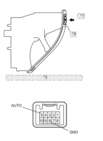
*1 Push *2 AUTO Switch *3 Component without harness connected: (Electric Parking Brake Switch) Measure the resistance according to the value(s) in the table below.
Standard resistance Tester Connection Switch Condition Specified Condition 5 (AUTO) - 8 (GND) AUTO switch is pressed and held Below 1 Ω AUTO switch OFF (released) 1 MΩ or higher
NG 
REPLACE ELECTRIC PARKING BRAKE SWITCH Click here
OK
-
-
CHECK HARNESS AND CONNECTOR (ECU - SWITCH)
-
Disconnect the S48 ECU connector.
-
Disconnect the L39 switch connector.
-
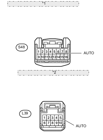
*1 Front view of wire harness connector: (to Electric Parking Brake ECU) *2 Front view of wire harness connector: (to Electric Parking Brake Switch) Measure the resistance according to the value(s) in the table below.
Standard resistance Tester Connection Condition Specified Condition S48-5 (AUTO) - L39-5 (AUTO) Always Below 5 Ω S48-5 (AUTO) - Body ground Always 100 kΩ or higher
NG
REPAIR OR REPLACE HARNESS OR CONNECTOR
OK
-
-
CHECK SHIFT LEVER POSITION SIGNAL (DATA LIST)
-
Turn the engine switch off.
-
Connect the intelligent tester to the DLC3.
-
Turn the engine switch on (IG) and the tester ON.
-
Enter the following menus:
Select: Chassis / Electric Parking Brake / Data List /
-
Check the values by referring to the table below.
Electric Parking Brake Tester Display Measurement Item/ Range Condition Normal Condition P Position Shift lever position input information display/
ON or OFF
Engine switch on (IG)
Shift lever is on P
ON: Shift lever is on P
OFF: Shift lever not on P
N Position Shift lever position input information display/
ON or OFF
Engine switch on (IG)
Shift lever is on N
ON: Shift lever is on N
OFF: Shift lever not on N
R Position Shift lever position input information display/
ON or OFF
Engine switch on (IG)
Shift lever is on R
ON: Shift lever is on R
OFF: Shift lever not on R
R Position Shift lever position input information display/
ON or OFF
Engine switch on (IG)
Shift lever is on D
ON: Shift lever is on D
OFF: Shift lever not on D
OK On tester screen, item changes between ON and OFF according to shift lever operation. Result Result Proceed to OK A NG (for AA80E) B NG (for AA80F) C
B
GO TO AUTOMATIC TRANSMISSION SYSTEM Click here
C
GO TO AUTOMATIC TRANSMISSION SYSTEM Click here
A
-
-
CHECK STOP LIGHT SWITCH SIGNAL (DATA LIST)
-
Turn the engine switch off.
-
Connect the intelligent tester to the DLC3.
-
Turn the engine switch on (IG) and the tester ON.
-
Enter the following menus:
Select: Chassis / Electric Parking Brake / Data List /
-
Check the values by referring to the table below.
Electric Parking Brake Tester Display Measurement Item/ Range Switch Condition Normal Condition Stop Light Switch Stop light switch input information display/
ON or OFF
Engine switch on (IG)
Stop light switch ON (brake pedal depressed)
ON: Stop light switch ON (brake pedal depressed)
OFF: Stop light switch OFF (brake pedal released)
OK On tester screen, item changes between ON and OFF according to switch operation.
NG
GO TO ELECTRONICALLY CONTROLLED BRAKE SYSTEM Click here
OK
-
-
CHECK AUTO SWITCH LIGHT OPERATION (ACTIVE TEST)
-
Turn the engine switch off.
-
Connect the intelligent tester to the DLC3.
-
Turn the engine switch on (IG) and the tester ON.
-
Enter the following menus:
Select: Chassis / Electric Parking Brake / Active Test /
-
Check the values by referring to the table below.
Electric Parking Brake Tester Display Test Part Control Range Diagnostic Note Auto Light AUTO switch light ON or OFF Vehicle speed is 0 km/h (0 mph) OK Indicator light turns on when operating the tester. Result Result Proceed to NG A OK B
B
REPLACE ELECTRIC PARKING BRAKE ECU Click here
A
-
-
INSPECT FUSE (D-IG1-3)
-
Remove the D-IG1-3 fuse from the main body ECU.
-
Measure the resistance according to the value(s) in the table below.
Standard resistance Tester Connection Condition Specified Condition D-IG1-3 fuse Always Below 1 Ω Result Result Proceed to NG A OK B
B
CHECK HARNESS AND CONNECTOR (SWITCH - BATTERY) Click here
A
-
-
CHECK HARNESS AND CONNECTOR (IND+ TERMINAL - BODY GROUND)
-
Disconnect the L39 switch connector.
-

*1 Front view of wire harness connector: (to Electric Parking Brake Switch) Measure the resistance according to the value(s) in the table below.
Standard resistance Tester Connection Condition Specified Condition L39-1 (IND+) - Body ground Always 10 kΩ or higher
NG
CHECK FOR SHORT IN ALL HARNESSES AND CONNECTORS CONNECTED TO FUSE AND REPLACE FUSE
OK
-
-
CHECK HARNESS AND CONNECTOR (LPA TERMINAL - BODY GROUND)
-
Disconnect the S46 ECU connector.
-
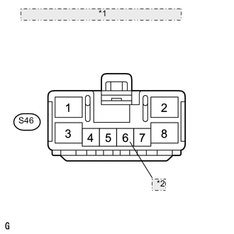
*1 Front view of wire harness connector: (to Electric Parking Brake ECU) *2 LPA Measure the resistance according to the value(s) in the table below.
Standard resistance Tester Connection Condition Specified Condition S46-6 (LPA) - Body ground Always 10 kΩ or higher
OK
REPLACE FUSE
NG
CHECK FOR SHORT IN ALL HARNESSES AND CONNECTORS CONNECTED TO FUSE AND REPLACE FUSE
-
-
CHECK HARNESS AND CONNECTOR (SWITCH - BATTERY)
-
Disconnect the L39 switch connector.
-
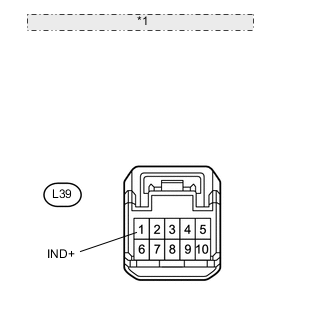
*1 Front view of wire harness connector: (to Electric Parking Brake Switch) Measure the voltage according to the value(s) in the table below.
Standard voltage Tester Connection Switch Condition Specified Condition L39-1 (IND+) - Body ground Engine switch on (IG) 11 to 14 V
NG
REPAIR OR REPLACE HARNESS OR CONNECTOR
OK
-
-
CHECK HARNESS AND CONNECTOR (SWITCH - ECU)
-
Disconnect the S46 ECU connector.
-
Disconnect the L39 switch connector.
-
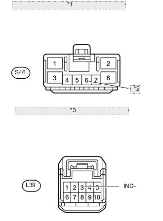
*1 Front view of wire harness connector: (to Electric Parking Brake ECU) *2 LPA *3 Front view of wire harness connector: (to Electric Parking Brake Switch) Measure the resistance according to the value(s) in the table below.
Standard resistance Tester Connection Condition Specified Condition S46-6 (LPA) - L39-3 (IND-) Always Below 5 Ω S46-6 (LPA) - Body ground Always 100 kΩ or higher
OK
REPLACE ELECTRIC PARKING BRAKE ECU Click here
NG
REPAIR OR REPLACE HARNESS OR CONNECTOR
-