BRAKE MASTER CYLINDER(for RHD) REASSEMBLY
PROCEDURE
-
ASSEMBLE BRAKE MASTER CYLINDER SUB-ASSEMBLY
-
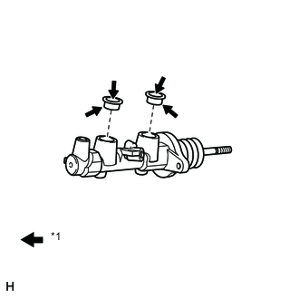
Text in Illustration *1 Lithium soap base glycol grease Apply a light coat of lithium soap base glycol grease to 2 new reservoir grommets and install them to the brake master cylinder with simulator.
-
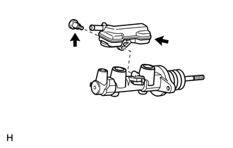
Install the brake master cylinder reservoir with the screw.
- Torque:
- 1.8 N*m { 18 kgf*cm, 16 in.*lbf }
-
-
TEMPORARILY INSTALL MASTER CYLINDER PUSH ROD CLEVIS
-
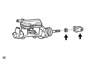
Temporarily install the lock nut and push rod clevis.
-
-
INSTALL BRAKE STROKE SIMULATOR CYLINDER SUB-ASSEMBLY
-
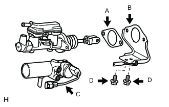
Install a new brake master cylinder gasket (labeled A), brake stroke simulator bracket (labeled B) and brake stroke simulator cylinder (labeled C) with the 2 bolts (labeled D).
- Torque:
- 8.0 N*m { 82 kgf*cm, 71 in.*lbf }
-
-
INSTALL BRAKE MASTER CYLINDER BRACKET
-
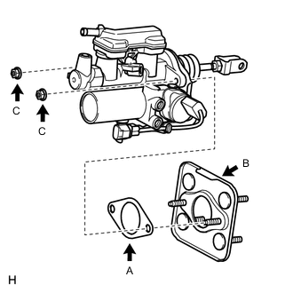
Install a new brake master cylinder gasket (labeled A) and brake master cylinder bracket (labeled B) to the brake master cylinder with simulator with the 2 nuts (labeled C).
- Torque:
- 13 N*m { 127 kgf*cm, 9 ft.*lbf }
-
-
INSTALL BRAKE STROKE SIMULATOR TUBE
-
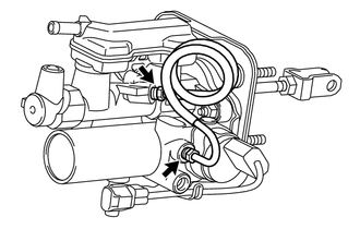
Using a union nut wrench, connect the brake stroke simulator tube to the brake master cylinder with simulator.
- Torque:
- 15 N*m { 155 kgf*cm, 11 ft.*lbf }
Note
Use the formula to calculate special torque values for situations where a union nut wrench is combined with a torque wrench Click here.
-
-
ADJUST MASTER CYLINDER PUSH ROD CLEVIS
-
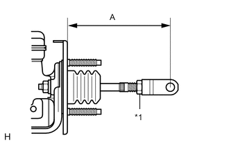
Text in Illustration *1 Lock Nut Adjust the master cylinder push rod clevis as shown in the illustration.
Length "A" 122.1 to 123.1 mm (4.807 to 4.846 in.) -
Tighten the lock nut.
- Torque:
- 26 N*m { 265 kgf*cm, 19 ft.*lbf }
-