| ECM |
Skid control ECU |
|
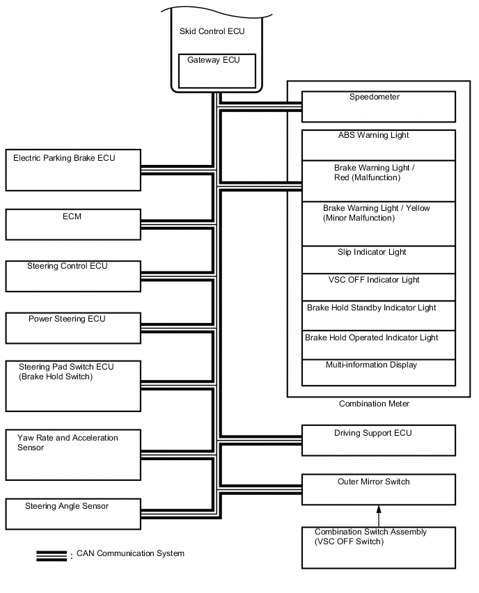
CAN communication system |
| Skid control ECU |
Yaw rate and acceleration sensor |
Yaw rate and acceleration request signal |
CAN communication system |
| Skid control ECU |
Steering angle sensor |
Steering angle sensor request signal |
CAN communication system |
| Skid control ECU |
ECM |
-
Wheel speed signal
-
VSC data signal
|
CAN communication system |
| Skid control ECU |
Combination meter |
-
ABS warning light ON signal
-
Brake warning light / Red (Malfunction) ON signal
-
Brake warning light / Yellow (Minor malfunction) ON signal
-
Slip indicator light ON signal
-
VSC OFF indicator light ON signal
-
TR(A)C OFF display ON signal
-
Speedometer signal
-
Brake hold standby indicator signal
-
Brake hold operated indicator signal
|
CAN communication system |
| Skid control ECU |
Power steering ECU |
Target additional torque signal |
CAN communication system |
| Power steering ECU |
Skid control ECU |
EPS cooperative control enabling signal |
CAN communication system |
| Skid control ECU |
Steering control ECU |
Target relative angle signal |
CAN communication system |
| Steering control ECU |
Skid control ECU |
|
CAN communication system |
| Distance control ECU |
Skid control ECU |
Brake control request signal |
CAN communication system |
| Steering Pad Switch ECU (Brake hold switch) |
Skid control ECU |
Brake hold request signal |
CAN communication system |