TOE CONTROL LINK INSTALLATION

CAUTION / NOTICE / HINT
Tech Tips
-
Use the same procedures for the RH side and LH side.
-
The procedures listed below are for the LH side.
-
A bolt without a torque specification is shown in the standard bolt chart Click here.
PROCEDURE
-
TEMPORARILY INSTALL TOE CONTROL LINK SUB-ASSEMBLY LH
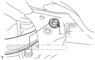
*1 Matchmark *2 No. 2 Suspension Toe Adjust Plate
-
Insert the toe adjust cam from the rear of the vehicle and connect the toe control link. Then temporarily install the No. 2 suspension toe adjust plate with the nut.
Note
Align the matchmarks of the No. 2 suspension toe adjust plate and suspension member.
-
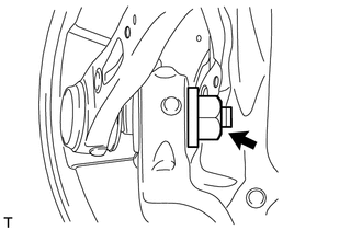
Temporarily install the toe control arm with the new nut to the axle carrier.
-
-
TIGHTEN TOE CONTROL LINK SUB-ASSEMBLY LH
-
Tighten the 2 nuts.
- Torque:
- 60 N*m { 612 kgf*cm, 44 ft.*lbf }
- for suspension member side
- 118 N*m { 1203 kgf*cm, 87 ft.*lbf }
- for axle carrier side
-
-
INSTALL REAR SPEED SENSOR LH
-
INSTALL LOAD SENSING VALVE SENSOR BRACKET
-
STABILIZE SUSPENSION
-
Stabilize the suspension (w/o Air Suspension) Click here.
-
Stabilize the suspension (w/ Air Suspension) Click here.
-
-
INSTALL REAR WHEEL
- Torque:
- 140 N*m { 1428 kgf*cm, 103 ft.*lbf }
-
CHECK SUSPENSION CONTROL SYSTEM (for Air suspension)
-
Check the suspension control system Click here.
-
-
INSPECT AND ADJUST REAR WHEEL ALIGNMENT
-
Inspect and adjust the rear wheel alignment Click here.
-
-
CHECK SPEED SENSOR SIGNAL
-
Check the speed sensor signal Click here.
-
-
ADJUST HEADLIGHT ASSEMBLY
-
ADJUST OBJECT RECOGNITION CAMERA