ELECTRONICALLY CONTROLLED BRAKE SYSTEM TS and CG Terminal Circuit
DESCRIPTION
In the sensor check mode, a malfunction of the speed sensor that cannot be detected when the vehicle is stopped is detected while driving.
Transition to the sensor check mode can be performed by connecting terminals TS and CG of the DLC3 and turning the engine switch from off to on (IG).
WIRING DIAGRAM
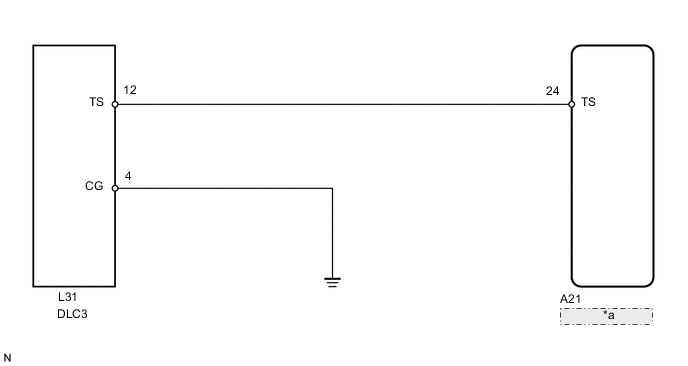
| *a | Skid Control ECU |
CAUTION / NOTICE / HINT
Note
When replacing the skid control ECU, perform initialization of linear solenoid valve calibration Click here.
PROCEDURE
-
CHECK HARNESS AND CONNECTOR (SKID CONTROL ECU - DLC3)
-
Turn the engine switch off.
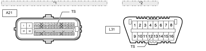
*1 Front view of wire harness connector: (to Skid Control ECU) *2 Front view of DLC3: -
Disconnect the A21 ECU connector.
-
Measure the resistance according to the value(s) in the table below.
Standard resistance Tester Connection Condition Specified Condition A21-24 (TS) - L31-12 (TS) Always Below 1 Ω
NG 
REPAIR OR REPLACE HARNESS OR CONNECTOR
OK 
-
-
CHECK HARNESS AND CONNECTOR (DLC3 - BODY GROUND)
-
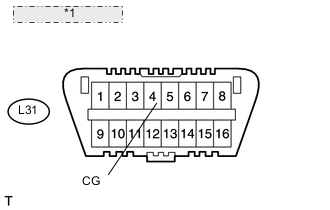
*1 Front view of DLC3: Measure the resistance according to the value(s) in the table below.
Standard resistance Tester Connection Condition Specified Condition L31-4 (CG) - Body ground Always Below 1 Ω
NG
REPAIR OR REPLACE HARNESS OR CONNECTOR
OK
-
-
CHECK HARNESS AND CONNECTOR (DLC3 - BODY GROUND)
-
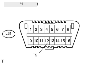
*1 Front view of DLC3: Measure the resistance according to the value(s) in the table below.
Standard resistance Tester Connection Condition Specified Condition L31-12 (TS) - Body ground Always 10 kΩ or higher Tech Tips
If troubleshooting has been carried out according to the "PROBLEM SYMPTOMS TABLE", refer back to the table and proceed to the next step before replacing the part Click here.
OK
REPLACE SKID CONTROL ECU Click here
NG
REPAIR OR REPLACE HARNESS OR CONNECTOR
-