FRONT LOWER SUSPENSION ARM(for 2WD) INSTALLATION

CAUTION / NOTICE / HINT
Tech Tips
-
Use the same procedures for the RH side and LH side.
-
The procedures listed below are for the LH side.
-
A bolt without a torque specification is shown in the standard bolt chart Click here.
PROCEDURE
-
TEMPORARILY TIGHTEN FRONT NO. 2 SUSPENSION LOWER ARM ASSEMBLY LH
-
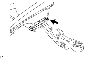
Insert the bolt from the front of the vehicle. Then temporarily install the front No. 2 suspension lower arm LH with the nut.
Tech Tips
Tighten the nut after the vehicle is stabilized.
-
Temporarily install the front No. 2 suspension lower arm LH to the steering knuckle with the nut.
Tech Tips
Tighten the nut after the vehicle is stabilized.
-
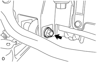
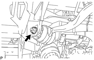
Install the bottom side of the pneumatic front LH with shock absorber cylinder assembly to the No. 2 suspension lower arm LH. Then insert the bolt from the rear of the vehicle and temporarily install it with the nut.
Tech Tips
Tighten the bolt after the vehicle is stabilized.
-
-
INSTALL FRONT STABILIZER LINK ASSEMBLY LH
-
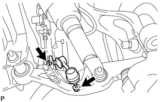
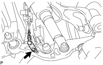
Install the front stabilizer link with the 2 nuts.
- Torque:
- 84 N*m { 857 kgf*cm, 62 ft.*lbf }
Tech Tips
If the ball joint turns together with the nut, use a 6 mm hexagon wrench to hold the stud.
-
-
CONNECT FRONT HEIGHT CONTROL SENSOR SUB-ASSEMBLY LH
-
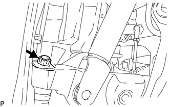
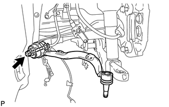
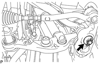
Install the bracket of the front height control sensor LH to the front No. 2 suspension lower arm LH with the bolt.
- Torque:
- 5.4 N*m { 55 kgf*cm, 48 in.*lbf }
-
-
TEMPORARILY TIGHTEN FRONT NO. 1 SUSPENSION LOWER ARM ASSEMBLY LH
-
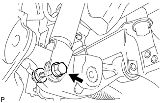
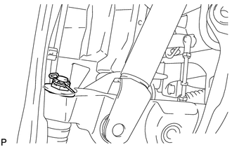
Insert the bolt from the back of the vehicle. Temporarily install the front No. 1 suspension lower arm LH with the nut.
Tech Tips
Tighten the nut after the vehicle is stabilized.
-

Temporarily install the front No. 1 suspension lower arm LH to the steering knuckle with the nut.
Tech Tips
Tighten the nut after the vehicle is stabilized.
-
-
INSTALL FRONT DISC BRAKE DUST COVER LH
-
INSTALL FRONT DISC
-
CONNECT FRONT DISC BRAKE CALIPER ASSEMBLY LH
-
CONNECT SPEED SENSOR CONNECTOR
-
INSTALL POWER STEERING LINK ASSEMBLY
-
w/ VGRS:
-
w/o VGRS:
-
-
STABILIZE SUSPENSION (w/o Air Suspension)
-
STABILIZE SUSPENSION (w/ Air suspension)
-
TIGHTEN FRONT NO. 2 SUSPENSION LOWER ARM ASSEMBLY LH
-
Tighten the installation nut of the front No. 2 suspension lower arm assembly LH.
- Torque:
- 145 N*m { 1479 kgf*cm, 107 ft.*lbf }
-
Tighten the installation nut of the steering knuckle.
- Torque:
- 145 N*m { 1479 kgf*cm, 107 ft.*lbf }
Note
If it is necessary to align the holes for the clips after installing the nuts, the nuts can be tightened up to 60° more.
-
Install a new clip.
-
Tighten the installation bolt of the shock absorber cylinder.
- Torque:
- 108 N*m { 1101 kgf*cm, 80 ft.*lbf }
-
-
TIGHTEN FRONT NO. 1 SUSPENSION LOWER ARM ASSEMBLY LH
-
Tighten the installation nut of the front No. 1 suspension upper arm assembly LH.
- Torque:
- 145 N*m { 1479 kgf*cm, 107 ft.*lbf }
-
Tighten the installation nut of the steering knuckle side.
- Torque:
- 145 N*m { 1479 kgf*cm, 107 ft.*lbf }
Note
If it is necessary to align the holes for the clips after installing the nuts, the nuts can be tightened up to 60° more.
-
Install a new clip.
-
-
INSPECT AND ADJUST FRONT WHEEL ALIGNMENT
-
Inspect and adjust the front wheel alignment Click here.
-
-
ADJUST HEADLIGHT ASSEMBLY
-
ADJUST OBJECT RECOGNITION CAMERA