REAR SUSPENSION MEMBER INSTALLATION

PROCEDURE
-
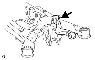
INSTALL REAR SUSPENSION MEMBER BODY MOUNTING CUSHION (for Rear Side)
-
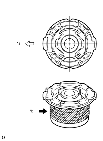
Apply soapy water around the outside of a new rear suspension member body mounting cushion.
Text in Illustration *a Front of Vehicle *b Apply Soapy Water -
Position the body mounting cushion as shown in the illustration, and install it to the rear suspension member.
-
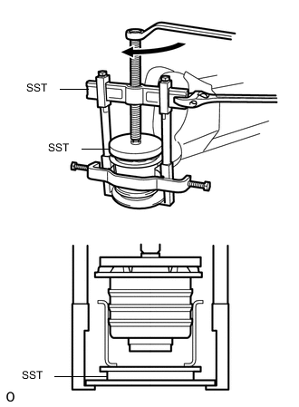
Using SST, press in the body mounting cushion.
- SST
- 09316-12010
- 09570-24011
- 09950-40011 ( 09951-04020, 09952-04010, 09953-04030, 09954-04020, 09955-04051, 09957-04010, 09958-04011 )
- 09950-60020 ( 09951-00910 )
Note
Do not apply excessive force to the inner cylinder of the body mounting cushion.
-
-
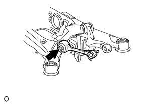
INSTALL REAR SUSPENSION MEMBER BODY MOUNTING CUSHION LH (for Front Side)
-
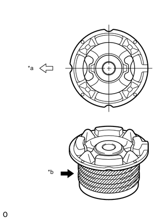
Apply soapy water around the outside of a new rear suspension member body mounting cushion.
Text in Illustration *a Front of Vehicle *b Apply Soapy Water -
Position the body mounting cushion as shown in the illustration, and install it to the rear suspension member.
-
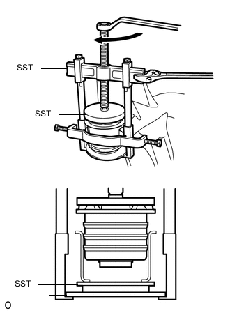
Using SST, press in the body mounting cushion.
- SST
- 09316-12010
- 09570-24011
- 09950-40011 ( 09951-04020, 09952-04010, 09953-04030, 09954-04020, 09955-04051, 09957-04010, 09958-04011 )
- 09950-60020 ( 09951-00910 )
Note
Do not apply excessive force to the inner cylinder of the body mounting cushion.
-
-
INSTALL REAR SUSPENSION MEMBER BODY MOUNTING CUSHION RH (for Front Side)
Tech Tips
Use the same procedure described for the LH side.
-
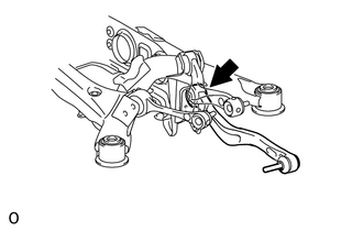
INSTALL REAR NO. 1 DIFFERENTIAL MOUNT CUSHION
-
INSTALL REAR NO. 2 DIFFERENTIAL MOUNT CUSHION
-
TEMPORARILY INSTALL REAR NO. 2 UPPER CONTROL ARM ASSEMBLY LH
-
Temporarily install the control arm with the bolt, nut and washer to the suspension member.
-
-
TEMPORARILY INSTALL REAR NO. 2 UPPER CONTROL ARM ASSEMBLY RH
Tech Tips
Use the same procedure described for the LH side.
-
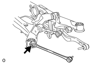
TEMPORARILY INSTALL REAR NO. 1 UPPER CONTROL ARM ASSEMBLY LH
-
Temporarily install the control arm with the bolt, nut and washer to the suspension member.
-
-
TEMPORARILY INSTALL REAR NO. 1 UPPER CONTROL ARM ASSEMBLY RH
Tech Tips
Use the same procedure described for the LH side.
-
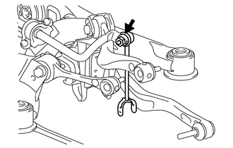
TEMPORARILY INSTALL TOE CONTROL LINK SUB-ASSEMBLY LH
-
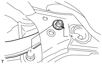
Insert the toe adjust cam from the front of the vehicle and connect the toe control link. Then temporarily install the No. 2 suspension toe adjust plate with the nut.
Text in Illustration *1 No. 2 Suspension Toe Adjust Plate *a Matchmark Note
Align the matchmarks of the No. 2 suspension toe adjust plate and suspension member.
-
-
TEMPORARILY INSTALL TOE CONTROL LINK SUB-ASSEMBLY RH
Tech Tips
Use the same procedure described for the LH side.
-
TEMPORARILY INSTALL REAR NO. 1 SUSPENSION ARM ASSEMBLY LH
-
Temporarily install the No. 1 suspension arm with the bolt and nut to the suspension member.
-
-
TEMPORARILY INSTALL REAR NO. 1 SUSPENSION ARM ASSEMBLY RH
Tech Tips
Use the same procedure described for the LH side.
-
INSTALL REAR SUSPENSION MEMBER DAMPER
-
INSTALL REAR STABILIZER BAR
-
INSTALL ELECTRIC PARKING BRAKE ACTUATOR
-
INSTALL REAR STABILIZER LINK ASSEMBLY LH
-
Install the stabilizer link with the nut to the stabilizer bar.
- Torque:
- 89 N*m { 908 kgf*cm, 66 ft.*lbf }
-
-
INSTALL REAR STABILIZER LINK ASSEMBLY RH
Tech Tips
Use the same procedure described for the LH side.
-
INSTALL REAR SUSPENSION MEMBER SUB-ASSEMBLY
-
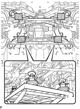
Text in Illustration *1 Attachment *2 Engine Lifter *a Attachment placement location Support the rear suspension member sub-assembly with an engine lifter using 4 attachments or equivalent tools.
Note
-
Make sure to secure the rear suspension member sub-assembly to prevent it from dropping.
-
Use the attachments to keep the rear suspension member sub-assembly level.
-
The rear suspension member sub-assembly is a heavy component. Make sure that it is supported securely.
-
-
Raise the rear suspension member sub-assembly until there is no clearance between the rear suspension member sub-assembly and the body.
Note
When raising the rear suspension member subassembly, be careful not to damage the vehicle body or other components installed on the vehicle.
-
for Sports Package:
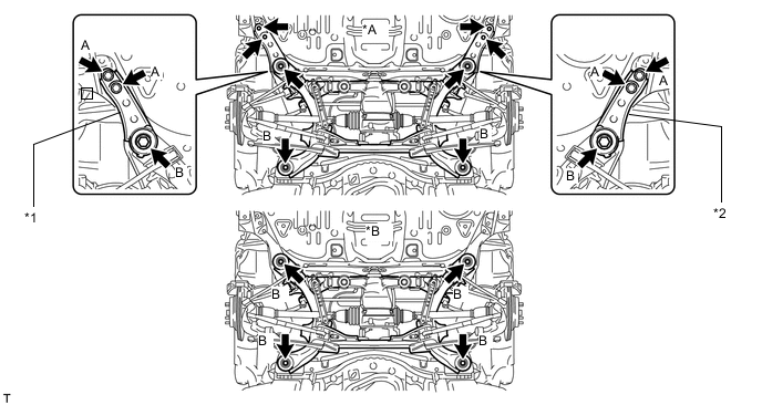
Text in Illustration *A for Sports Package *B for Standard *1 Suspension Member Stopper Lower RH *2 Suspension Member Stopper Lower LH
-
Install the 2 member stoppers with the 4 bolts labeled B, and install the 4 bolts labeled A.
- Torque:
- for bolt A
- 19 N*m { 194 kgf*cm, 14 ft.*lbf }
- for bolt B
- 127 N*m { 1295 kgf*cm, 94 ft.*lbf }
-
-
for Standard:
-
Install the 4 bolts labeled B.
- Torque:
- 127 N*m { 1295 kgf*cm, 94 ft.*lbf }
-
-
-
INSTALL REAR DIFFERENTIAL CARRIER ASSEMBLY WITH DRIVE SHAFT
-
INSTALL REAR AXLE ASSEMBLY LH
-
INSTALL REAR AXLE ASSEMBLY RH
Tech Tips
Use the same procedure described for the LH side.
-
INSTALL LOAD SENSING VALVE SENSOR BRACKET
-
INSTALL REAR HEIGHT CONTROL SENSOR SUB-ASSEMBLY LH
-
INSTALL REAR HEIGHT CONTROL SENSOR SUB-ASSEMBLY RH
Tech Tips
Use the same procedure described for the LH side.
-
INSTALL PROPELLER SHAFT WITH CENTER BEARING ASSEMBLY
-
CONNECT NO. 1 ACTUATOR HARNESS CLAMP
-
INSTALL REAR WHEEL HOUSE LINER LH
-
STABILIZE SUSPENSION (w/o Air Suspension)
-
STABILIZE SUSPENSION (w/ Air Suspension)
-
TIGHTEN REAR NO. 2 UPPER CONTROL ARM ASSEMBLY LH
-
TIGHTEN REAR NO. 2 UPPER CONTROL ARM ASSEMBLY RH
Tech Tips
Use the same procedure described for the LH side.
-
TIGHTEN REAR NO. 1 UPPER CONTROL ARM ASSEMBLY LH
-
TIGHTEN REAR NO. 1 UPPER CONTROL ARM ASSEMBLY RH
Tech Tips
Use the same procedure described for the LH side.
-
TIGHTEN TOE CONTROL LINK SUB-ASSEMBLY LH
-
TIGHTEN TOE CONTROL LINK SUB-ASSEMBLY RH
Tech Tips
Use the same procedure described for the LH side.
-
TIGHTEN REAR NO. 1 SUSPENSION ARM ASSEMBLY LH
-
TIGHTEN REAR NO. 1 SUSPENSION ARM ASSEMBLY RH
Tech Tips
Use the same procedure described for the LH side.
-
INSPECT REAR NO. 1 UPPER CONTROL ARM BALL JOINT LOOSENESS
-
INSPECT REAR NO. 2 UPPER CONTROL ARM BALL JOINT LOOSENESS
-
INSPECT REAR NO. 1 SUSPENSION ARM BALL JOINT LOOSENESS
-
INSPECT TOE CONTROL LINK BALL JOINT LOOSENESS
-
CHECK VEHICLE HEIGHT
-
ADJUST VEHICLE HEIGHT
-
INSPECT AND ADJUST REAR WHEEL ALIGNMENT
-
ADJUST HEADLIGHT ASSEMBLY
-
ADJUST OBJECT RECOGNITION CAMERA