AIR SUSPENSION SYSTEM TC and CG Terminal Circuit
DESCRIPTION
DTC output mode is set by connecting terminals 13 (TC) and 4 (CG) of the DLC3. The DTCs are indicated by the blinking of the "HEIGHT HIGH" indicator light.
WIRING DIAGRAM
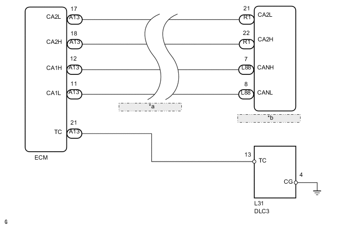
| *a | CAN Communication Line |
| *b | Suspension Control ECU |
PROCEDURE
-
INSPECT DLC3 (TC VOLTAGE)
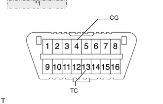
*1 Front view of DLC3:
-
Measure the voltage according to the value in the table below.
Standard voltage Tester Connection Switch Condition Specified Condition L31-13 (TC) - L31-4 (CG) Engine switch on (IG) 10 to 14 V Result Result Proceed to NG A OK B
B 
PROCEED TO NEXT CIRCUIT INSPECTION SHOWN IN PROBLEM SYMPTOMS TABLE Click here
A 
-
-
CHECK HARNESS AND CONNECTOR (DLC3 - ECM AND BODY GROUND)
-
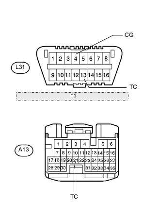
Front view of DLC3 *1 Front view of wire harness connector: (to ECM) Disconnect the A13 ECM connector.
-
Measure the resistance according to the value in the table below.
Standard resistance Tester Connection Switch Condition Specified Condition L31-13 (TC) - A13-21 (TC) Always Below 1 Ω L31-13 (TC) or A13-21 (TC) - Body ground Always 10 kΩ or higher L31-4 (CG) - Body ground Always Below 1 Ω Result Result Proceed to NG A OK (1UR-FSE) B OK (1UR-FE) C
A
REPAIR OR REPLACE HARNESS OR CONNECTOR
B
REPLACE ECM (1UR-FSE) Click here
C
REPLACE ECM (1UR-FE) Click here
-