AIR SUSPENSION SYSTEM, Diagnostic DTC:C1752
| DTC Code | DTC Name |
|---|---|
| C1752 | Height Control Compressor Motor Circuit Malfunction |
DESCRIPTION
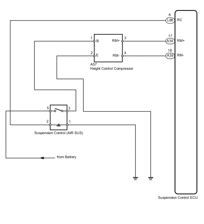
The signal from the suspension control ECU turns on the suspension control relay. At that time, battery voltage is input to the height control compressor motor through the suspension control relay. The height control compressor motor starts.
| DTC No. | Detection Condition | Trouble Area |
|---|---|---|
| C1752/52 | With the suspension control relay activated, a lock signal of the height control compressor motor is detected for 4 sec. or more. |
|
WIRING DIAGRAM
CAUTION / NOTICE / HINT
Note
-
Before performing troubleshooting, inspect the connectors of related circuits.
-
Before replacing the suspension control ECU, perform all of the following again: 1) symptom simulation Click here; 2) DTC inspection; and 3) intelligent tester inspection (ECU Data List or Active Test). If no malfunctions are found in other areas, replace the suspension control ECU.
-
If the suspension control ECU or height control sensor is replaced, the vehicle height offset calibration must be performed Click here.
PROCEDURE
-
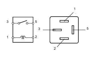
INSPECT SUSPENSION CONTROL RELAY (AIR SUS)
-
Turn the engine switch off.
-
Remove the suspension control relay from the engine room No. 1 relay block.
-
Measure the resistance according to the value(s) in the table below.
Standard resistance Tester Connection Condition Specified Condition 3 - 5 When battery voltage is not applied to terminal 1 and 2 10 kΩ or higher When battery voltage is applied to terminal 1 and 2 Below 1 Ω
NG 
REPLACE SUSPENSION CONTROL RELAY
OK 
-
-
CHECK HARNESS AND CONNECTOR (ECU - COMPRESSOR, COMPRESSOR - BATTERY AND BODY GROUND)
-
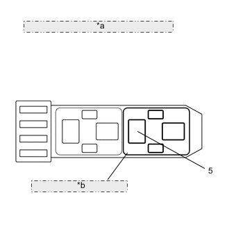
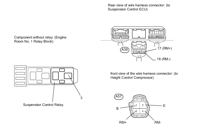
*a Component without relay: (Engine Room No. 1 Relay Block) *b Suspension Control Relay Remove the suspension control relay from the engine room No. 1 relay block.
-
Measure the voltage according to the value(s) in the table below.
Standard voltage Tester Connection Condition Specified Condition Relay block suspension control relay terminal 5 - Body ground Always 11 to 14 V -
Disconnect the A57 compressor connector.
-
Disconnect the A39 ECU connector.
-
Measure the resistance according to the value(s) in the table below.
Standard resistance Tester Connection Condition Specified Condition Relay block suspension control relay terminal 3 - A57-1 (B) Always Below 1 Ω Relay block suspension control relay terminal 3 or A57-1 (B) - Body ground Always 10 kΩ or higher A57-2 (E) - Body ground Always Below 1 Ω A57-3 (RM+) - A39-17 (RM+) Always Below 1 Ω A57-3 (RM+) or A39-17 (RM+) - Body ground Always 10 kΩ or higher A57-4 (RM-) - A39-18 (RM-) Always Below 1 Ω A57-4 (RM-) or A39-18 (RM-) - Body ground Always 10 kΩ or higher
NG
REPAIR OR REPLACE HARNESS OR CONNECTOR
OK
-
-
INSPECT HEIGHT CONTROL COMPRESSOR (COMPRESSOR MOTOR)
-
Remove the height control compressor Click here.
-
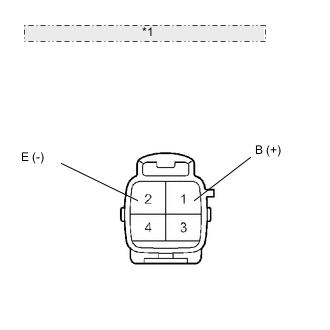
*1 Component without harness connected: (Height Control Compressor) Connect terminal 1 (B) to the battery positive (+) terminal, and terminal 2 (E) to the battery negative (-) terminal.
-
Check the operating of the compressor motor.
OK Motor operates Note
-
Do not operate the height control compressor for 60 seconds or more.
-
Since a short and a lock-up inside the height control compressor cause excessive current to flow, stop operation immediately when it does not rotate.
Result Result Proceed to NG A OK (for LHD) B OK (for RHD) C -
A
REPLACE HEIGHT CONTROL COMPRESSOR Click here
B
REPLACE SUSPENSION CONTROL ECU (for LHD) Click here
C
REPLACE SUSPENSION CONTROL ECU (for RHD) Click here
-