VVT SENSOR INSTALLATION
PROCEDURE
-
INSTALL VVT SENSOR
-
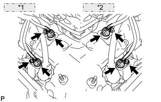
*1 for Bank 2: *2 for Bank 1: Install the 4 VVT sensors with the 4 bolts.
- Torque:
- 10 N*m { 102 kgf*cm, 7 ft.*lbf }
-
Connect the 4 VVT sensor connectors.
-
-
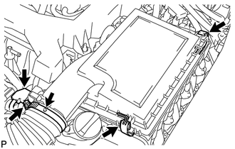
INSTALL AIR CLEANER ASSEMBLY RH
-
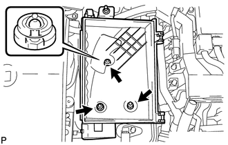
Install the air cleaner case with the 2 nuts and clip.
- Torque:
- 5.0 N*m { 51 kgf*cm, 44 in.*lbf }
-
Install the element to the air cleaner case.
-
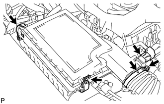
Install the air cleaner cap sub-assembly RH to the air cleaner case with the 2 clips.
- Torque:
- 3.8 N*m { 39 kgf*cm, 34 in.*lbf }
Tech Tips
-
Insert the protrusion of the air cleaner hose into the hole of the hose clamp.
-
The hose clamp can be tightened within the range of 2.0 N*m (20 kgf*cm, 18 in.*lbf) to 5.5 N*m (56 kgf*cm, 49 in.*lbf).
-
Connect the mass air flow meter connector.
-
-
INSTALL AIR CLEANER ASSEMBLY LH
-
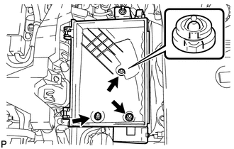
Install the air cleaner case with the 2 nuts and clip.
- Torque:
- 5.0 N*m { 51 kgf*cm, 44 in.*lbf }
-
Install the element to the air cleaner case.
-
Install the air cleaner cap sub-assembly LH to the air cleaner case with the 2 clips.
- Torque:
- 3.8 N*m { 39 kgf*cm, 34 in.*lbf }
Tech Tips
-
Insert the protrusion of the air cleaner hose into the hole of the hose clamp.
-
The hose clamp can be tightened within the range of 2.0 N*m (20 kgf*cm, 18 in.*lbf) to 5.5 N*m (56 kgf*cm, 49 in.*lbf).
-
Connect the mass air flow meter connector.
-
-
INSTALL NO. 1 AIR CLEANER INLET
-
INSTALL AIR CLEANER INLET COVER SUB-ASSEMBLY
-
INSTALL V-BANK COVER SUB-ASSEMBLY