VVT SENSOR REMOVAL
PROCEDURE
-
REMOVE V-BANK COVER SUB-ASSEMBLY
-
REMOVE AIR CLEANER INLET COVER SUB-ASSEMBLY
-
REMOVE NO. 1 AIR CLEANER INLET
-
REMOVE AIR CLEANER ASSEMBLY LH
-
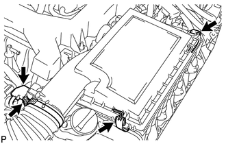
Disconnect the mass air flow meter connector.
-
Remove the 2 clamps, loosen the hose clamp and remove the air cleaner cap sub-assembly LH.
-
Remove the element from the air cleaner case.
-
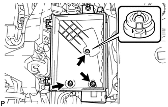
Remove the 2 nuts, clip and air cleaner case.
-
-
REMOVE AIR CLEANER ASSEMBLY RH
-
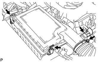
Disconnect the mass air flow meter connector.
-
Remove the 2 clamps, loosen the hose clamp and remove the air cleaner cap sub-assembly RH.
-
Remove the element from the air cleaner case.
-
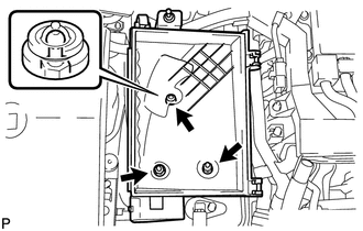
Remove the 2 nuts, clip and air cleaner case.
-
-
REMOVE VVT SENSOR
-
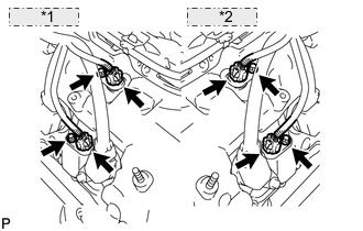
*1 for Bank 2: *2 for Bank 1: Disconnect the 4 VVT sensor connectors.
-
Remove the 4 bolts and 4 VVT sensors.
-