VVT SENSOR ON-VEHICLE INSPECTION
PROCEDURE
-
CHECK VVT SENSOR OUTPUT VOLTAGE
-
Turn the engine switch on (IG).
-
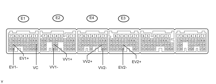
Measure the voltage according to the value(s) in the table below.
Standard Voltage Tester Connection Condition Specified Condition E1-18 (VC) - E2-33 (VV1-) Engine switch on (IG) 5 V E1-18 (VC) - E4-29 (VV2-) Engine switch on (IG) 5 V E1-18 (VC) - E1-33 (EV1-) Engine switch on (IG) 5 V E1-18 (VC) - E3-29 (EV2-) Engine switch on (IG) 5 V -
While turning the crankshaft pulley by hand, measure the voltage between each terminal. Check that the voltage changes between the Hi range and Lo range shown in the table below.
Standard Voltage Sensor Position Tester Connection Condition Specified Condition Bank 1 (Intake side) E2-25 (VV1+) - E2-33 (VV1-) Engine switch on (IG) 3.75 to 4.50 V Voltage (Hi)
0.50 to 1.25 V Voltage (Lo)
Bank 2 (Intake side) E4-19 (VV2+) - E4-29 (VV2-) Engine switch on (IG) 3.75 to 4.50 V Voltage (Hi)
0.50 to 1.25 V Voltage (Lo)
Bank 1 (Exhaust side) E1-26 (EV1+) - E1-33 (EV1-) Engine switch on (IG) 3.75 to 4.50 V Voltage (Hi)
0.50 to 1.25 V Voltage (Lo)
Bank 2 (Exhaust side) E3-22 (EV2+) - E3-29 (EV2-) Engine switch on (IG) 3.75 to 4.50 V Voltage (Hi)
0.50 to 1.25 V Voltage (Lo)
-