SFI SYSTEM, Diagnostic DTC:P0016, P0018
| DTC Code | DTC Name |
|---|---|
| P0016 | Crankshaft Position - Camshaft Position Correlation (Bank 1 Sensor A) |
| P0018 | Crankshaft Position - Camshaft Position Correlation (Bank 2 Sensor A) |
DESCRIPTION
Refer to DTC P0010 Click here.
| DTC No. | DTC Detection Condition | Trouble Area |
|---|---|---|
| P0016 | Valve timing on bank 1 intake side is deviated for 60 seconds or more (2 trip detection logic) |
|
| P0018 | Valve timing on bank 2 intake side is deviated for 60 seconds or more (2 trip detection logic) |
|
MONITOR DESCRIPTION
These DTCs are output when a valve timing deviation condition is detected. While the vehicle is being driven or the engine is idling (after the battery terminals are reconnected), if a valve timing deviation is detected during the valve timing initialization operation, it is determined that a malfunction has occurred. If this condition is detected while driving, a DTC is output (2 trip detection logic). However, if the valve timing is deviated, the camshaft position sensor malfunction DTC P1340 may be output.
A DTC is output if the following occurs: 1) the engine is idled, and then the engine switch is turned off; and 2) the engine is started and the engine is idled.
Tech Tips
DTC P0016 and/or P0018 may be output if the battery is reconnected and the engine is started while the following are disconnected from the camshaft timing control motor: 1) power source harness or connector; or 2) ECM harness or connector.
If P0016 and/or P0018 is output, check if the harness or connector is disconnected.
CAUTION / NOTICE / HINT
Tech Tips
Intelligent tester only:
By using the Active Test's Control the VVT-iE Linear (Bank 1) or Control the VVT-iE Linear (Bank 2) function, it can be determined if the VVT-iE system is malfunctioning.
-
Connect the intelligent tester to the DLC3.
-
Turn the engine switch on (IG) and turn the tester ON.
-
Clear the DTC Click here.
-
Start the engine and warm it up.
-
Enter the following menus: Powertrain / Engine / Active Test / Control the VVT-iE Linear (Bank 1) or Control the VVT-iE Linear (Bank 2) / All Data / VVT-iE Aim Angle #1 and VVT Change Angle #1 or VVT-iE Aim Angle #2 and VVT Change Angle #2.
-
Perform the "Control the VVT-iE Linear (Bank 1) or Control the VVT-iE Linear (Bank 2)" operation with the engine speed at 1500 rpm.
OK Active Test Movement Order Difference between "VVT-iE Aim Angle" and "VVT Change Angle" 0 deg → 10 deg → 20 deg → 40 deg → 10 deg → 0 deg → 10 deg → END Within 4 DegFR
Tech Tips
Read freeze frame data using the intelligent tester. Freeze frame data records the engine conditions when malfunctions are detected. When troubleshooting, freeze frame data can help determine if the vehicle was moving or stationary, if the engine was warmed up or not, if the air-fuel ratio was lean or rich, and other data from the time the malfunction occurred.
PROCEDURE
-
CHECK ANY OTHER DTCS OUTPUT (IN ADDITION TO DTC P0016 OR P0018)
-
Connect the intelligent tester to the DLC3.
-
Turn the engine switch on (IG).
-
Turn the tester ON.
-
Enter the following menus: Powertrain / Engine /DTC.
-
Read DTCs.
Result Display (DTC Output) Proceed to P0016 or P0018 A P0016 or P0018 and other DTCs B
B 
GO TO DTC CHART Click here
A 
-
-
INSPECT CAMSHAFT TIMING GEAR ASSEMBLY (BANK 1 AND/OR BANK 2)
-
Turn the engine switch off.
-
Remove the camshaft timing control motor Click here.
-
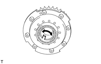
Check if the camshaft timing gear assembly's eccentric shaft rotates smoothly.
OK Rotates smoothly
NG
REPLACE CAMSHAFT TIMING GEAR ASSEMBLY (BANK 1 AND/OR BANK 2) Click here
OK
-
-
CHECK VALVE TIMING
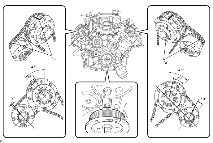
*a Timing Mark
-
Remove the cylinder head cover bank 1 and bank 2.
-
Turn the crankshaft pulley, and align its groove with the timing mark "0" of the timing chain cover.
-
Rotate the crankshaft pulley and align its notch to timing mark 0 of the timing chain cover. Check that the timing marks of the camshaft timing gears and camshaft timing exhaust gears are at the positions shown in the illustration.
OK Timing marks on camshaft timing gears are aligned as shown in the illustration. -
Reinstall the cylinder head cover.
NG
ADJUST VALVE TIMING Click here
OK
-
-
CONFIRM WHETHER MALFUNCTION HAS BEEN SUCCESSFULLY REPAIRED
-
To initialize the ECM's valve timing, disconnect the cable from the negative (-) battery terminal for 1 minute.
-
Connect the cable to the negative (-) battery terminal.
-
Connect the intelligent tester to the DLC3.
-
Switch the ECM from normal mode to check mode using the intelligent tester Click here.
-
Start the engine and idle it for 5 minutes.
-
Drive the vehicle in an urban area for approximately 10 minutes.
-
Enter the following menus: Powertrain / Engine / DTC.
-
Read DTCs.
Result Display (DTC Output) Proceed to No output A Other DTCs B
A
END
B
GO TO DTC CHART Click here
-