OIL PUMP INSPECTION

PROCEDURE
-
INSPECT STATOR SHAFT SPRING SUB-ASSEMBLY
-
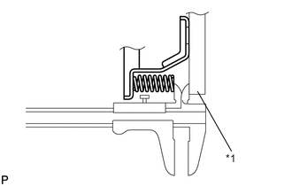
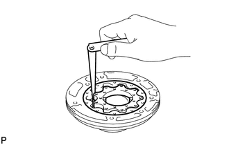
Using a vernier caliper and straightedge, measure the distance between the spring end and the straightedge.
Standard distance 6.52 mm (0.257 in.) Text in Illustration *1 Straightedge
-
-
INSPECT FRONT OIL PUMP BODY SUB-ASSEMBLY
-
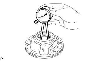
Using a caliper gauge, measure the inside diameter of the front oil pump body bush.
Maximum inside diameter 45.078 mm (1.77 in.) If the inside diameter is more than the maximum, replace the front oil pump body sub-assembly.
-
-
INSPECT STATOR SHAFT ASSEMBLY
-
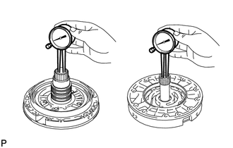
Using a caliper gauge, measure the inside diameter of the stator shaft bush.
Maximum inside diameter Front side 25.925 mm (1.02 in.) Rear side 35.251 mm (1.39 in.) If the inside diameter is more than the maximum, replace the stator shaft assembly.
-
-
INSPECT CLEARANCE OF OIL PUMP ASSEMBLY
-
Push the front oil pump driven gear to one side of the front oil pump body sub-assembly.
-
Using a feeler gauge, measure the clearance between the front oil pump driven gear and front oil pump body sub-assembly.
Standard body clearance 0.10 to 0.17 mm (0.00394 to 0.00669 in.) If the body clearance is not as specified, replace the front oil pump drive gear, front oil pump driven gear and front oil pump body sub-assembly.
-
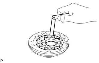
Using a feeler gauge, measure the clearance between the front oil pump driven gear teeth and front oil pump drive gear teeth.
Standard tip clearance 0.07 to 0.15 mm (0.00276 to 0.00591 in.) If the tip clearance is not as specified, replace the front oil pump drive gear, front oil pump driven gear and front oil pump body sub-assembly.
-
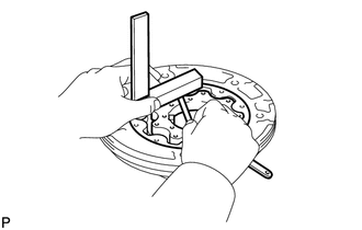
Using a steel straightedge and feeler gauge, measure the clearance between both gears and the straightedge.
Standard side clearance 0.03 to 0.05 mm (0.00118 to 0.00197 in.) If the side clearance is not as specified, replace the front oil pump drive gear, front oil pump driven gear and front oil pump body sub-assembly.
Tech Tips
There are 7 different thicknesses for the drive and driven gears.
Standard drive and driven gears thickness Mark Thickness 0 11.636 to 11.642 mm (0.4581 to 0.4583 in.) 1 11.643 to 11.649 mm (0.4584 to 0.4586 in.) 2 11.650 to 11.656 mm (0.4587 to 0.4589 in.) 3 11.657 to 11.663 mm (0.4589 to 0.4592 in.) 4 11.664 to 11.670 mm (0.4592 to 0.4594 in.) 5 11.671 to 11.677 mm (0.4595 to 0.4597 in.) 6 11.678 to 11.684 mm (0.4598 to 0.4600 in.)
-
-
INSPECT OIL PUMP DRIVE GEAR ROTATION
-
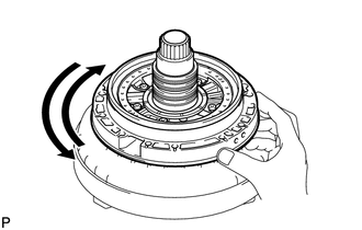
Place the oil pump assembly on the torque converter.
-
Make sure that the front oil pump drive gear rotates smoothly.
-