AUTOMATIC TRANSMISSION SYSTEM Shift Paddle Switch Circuit
DESCRIPTION
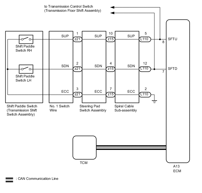
When the shift lever is in M, the shift range can be changed using the shift paddle switches. It is also possible to select the shift range when the vehicle is being driven with the shift lever in D by operating the shift paddle switches.
WIRING DIAGRAM
PROCEDURE
-
CHECK HARNESS AND CONNECTOR (SPIRAL CABLE - BODY GROUND)
-
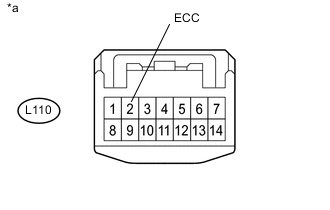
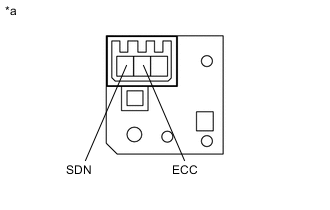
Text in Illustration *a Front view of wire harness connector
(to Spiral Cable Sub-assembly)
Disconnect the spiral cable connector.
-
Measure the resistance according to the value(s) in the table below.
Standard Resistance Tester Connection Condition Specified Condition L110-2 (ECC) - Body ground Always Below 1 Ω
NG 
REPAIR OR REPLACE HARNESS OR CONNECTOR
OK 
-
-
INSPECT SPIRAL CABLE SUB-ASSEMBLY
-
Remove the spiral cable sub-assembly Click here.
-
Set the spiral cable to the center position.
-
Measure the resistance according to the value(s) in the table below.
-
After setting the spiral cable to the center position, rotate the spiral cable 2.5 times clockwise and measure the resistance. Then rotate the spiral cable 2.5 times counterclockwise and measure the resistance.
-
After setting the spiral cable to the center position, rotate the spiral cable 2.5 times clockwise. Then while rotating the spiral cable 5 times counterclockwise, measure the resistance.
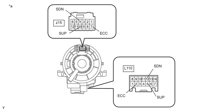
Standard Resistance Tester Connection Condition Specified Condition z15-10 (SUP) - L110-5 (SUP) Always Below 1 Ω z15-4 (SDN) - L110-12 (SDN) Always Below 1 Ω z15-7 (ECC) - L110-2 (ECC) Always Below 1 Ω Note
As the spiral cable may break, do not rotate the spiral cable more than the specified amount.
Text in Illustration *a Component without harness connected
(Spiral Cable Sub-assembly)
-
NG
REPLACE SPIRAL CABLE SUB-ASSEMBLY Click here
OK
-
-
INSPECT TRANSMISSION SHIFT SWITCH ASSEMBLY (RH (+))
-
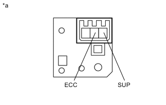
Text in Illustration *a Component without harness connected
(Transmission Shift Switch Assembly (RH (+)))
Remove the transmission shift switch RH Click here.
-
Measure the resistance according to the value(s) in the table below.
Standard Resistance Tester Connection Switch Condition Specified Condition SUP - ECC "+" shift paddle operated and held (up-shift) Below 2.5 Ω SUP - ECC "+" shift paddle not operated (up-shift) 1 MΩ or higher
NG
REPLACE TRANSMISSION SHIFT SWITCH ASSEMBLY (RH (+)) Click here
OK
-
-
INSPECT TRANSMISSION SHIFT SWITCH ASSEMBLY (LH (-))
-
Text in Illustration *a Component without harness connected
(Transmission Shift Switch Assembly (LH (-)))
Remove the transmission shift switch LH Click here.
-
Measure the resistance according to the value(s) in the table below.
Standard Resistance Tester Connection Switch Condition Specified Condition SDN - ECC "-" shift paddle operated and held (down-shift) Below 2.5 Ω SDN - ECC "-" shift paddle not operated (down-shift) 1 MΩ or higher
NG
REPLACE TRANSMISSION SHIFT SWITCH ASSEMBLY (LH (-)) Click here
OK
-
-
INSPECT NO.1 SWITCH WIRE
-
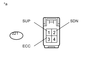
Text in Illustration *a Component without harness connected
(No. 1 switch wire)
Disconnect the No. 1 switch wire connector from the steering pad switch.
-
Measure the resistance according to the value(s) in the table below.
Standard Resistance Tester Connection Switch Condition Specified Condition z21-1 (SUP) - z21-3 (ECC) "+" shift paddle operated and held (up-shift) Below 2.5 Ω z21-1 (SUP) - z21-3 (ECC) "+" shift paddle not operated (up-shift) 1 MΩ or higher z21-2 (SDN) - z21-3 (ECC) "-" shift paddle operated and held (down-shift) Below 2.5 Ω z21-2 (SDN) - z21-3 (ECC) "-" shift paddle not operated (down-shift) 1 MΩ or higher
NG
REPLACE NO.1 SWITCH WIRE Click here
OK
-
-
INSPECT STEERING PAD SWITCH ASSEMBLY
-
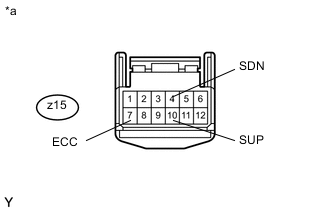
Text in Illustration *a Front view of wire harness connector
(to Spiral Cable Sub-assembly)
Disconnect the steering pad switch assembly connector.
-
Measure the resistance according to the value(s) in the table below.
Standard Resistance Tester Connection Switch Condition Specified Condition z15-10 (SUP) - z15-7 (ECC) "+" shift paddle operated and held (up-shift) Below 2.5 Ω z15-4 (SDN) - z15-7 (ECC) "-" shift paddle operated and held (down-shift) Below 2.5 Ω z15-10 (SUP) - z15-7 (ECC) "+" shift paddle not operated (up-shift) 1 MΩ or higher z15-4 (SDN) - z15-7 (ECC) "-" shift paddle not operated (down-shift) 1 MΩ or higher
NG
REPLACE STEERING PAD SWITCH ASSEMBLY Click here
OK
-
-
CHECK HARNESS AND CONNECTOR (SPIRAL CABLE - ECM)
-
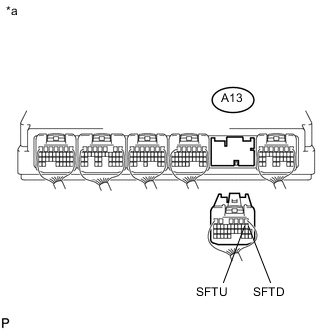
Text in Illustration *a Rear view of wire harness connector
(to ECM)
Disconnect the ECM connector.
-
Disconnect the transmission control switch (transmission floor shift assembly) connector.
-
Measure the resistance according to the value(s) in the table below.
Standard Resistance Tester Connection Switch Condition Specified Condition A13-8 (SFTU) - Body ground "+" shift paddle operated and held (up-shift) Below 2.5 Ω A13-7 (SFTD) - Body ground "-" shift paddle operated and held (down-shift) Below 2.5 Ω A13-8 (SFTU) - Body ground "+" shift paddle not operated (up-shift) 1 MΩ or higher A13-7 (SFTD) - Body ground "-" shift paddle not operated (down-shift) 1 MΩ or higher
OK
PROCEED TO NEXT SUSPECTED AREA SHOWN IN PROBLEM SYMPTOMS TABLE Click here
NG
REPAIR OR REPLACE HARNESS OR CONNECTOR
-