AUTOMATIC TRANSMISSION SYSTEM, Diagnostic DTC:P0617
| DTC Code | DTC Name |
|---|---|
| P0617 | Starter Relay Circuit High |
DESCRIPTION
While the engine is being cranked, the positive battery voltage is applied to terminal STA of the TCM.
If the TCM detects the Starter Control (STA) signal while the vehicle is being driven, it determines that there is a malfunction in the STA circuit. The TCM then illuminates the MIL and sets the DTC.
This monitor runs when the vehicle is driven at 12.4 mph (20 km/h) for over 20 seconds.
| DTC No. | DTC Detection Condition | Trouble Area |
|---|---|---|
| P0617 | When conditions (a), (b) and (c) are met, positive (+B) battery voltage of 10.5 V or more is applied to TCM for 20 seconds (1 trip detection logic)
|
|
WIRING DIAGRAM
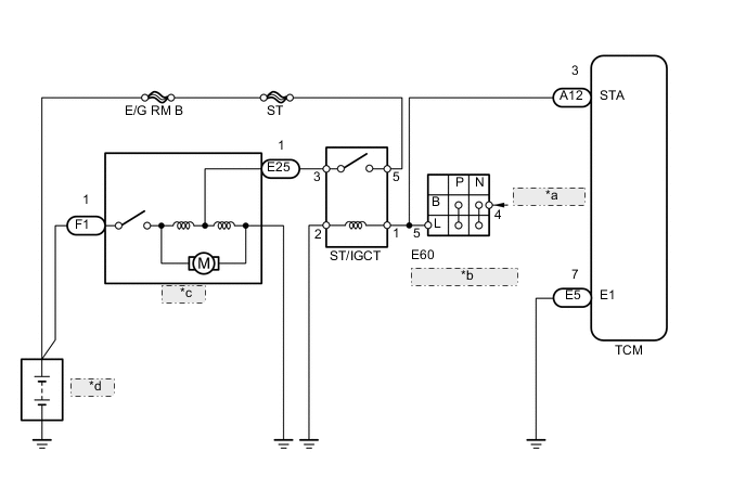
| *a | from Main Body ECU |
| *b | Park/Neutral Position Switch |
| *c | Starter |
| *d | Battery |
PROCEDURE
-
READ VALUE USING DATA LIST (STARTER SIGNAL)
-
Connect the intelligent tester to the DLC3.
-
Turn the engine switch on (IG) and turn the intelligent tester ON.
-
Enter the following menus: Powertrain / ECT / Data List.
-
Read the value displayed on the tester.
-
Crank the engine.
-
Read the value displayed on the tester.
OK Tester Display Condition Standard Starter Signal Engine switch on (IG) OFF Starter Signal Engine is cranking ON
NG 
INSPECT PARK/NEUTRAL POSITION SWITCH Click here
OK 
-
-
CHECK TCM (STA VOLTAGE)
-
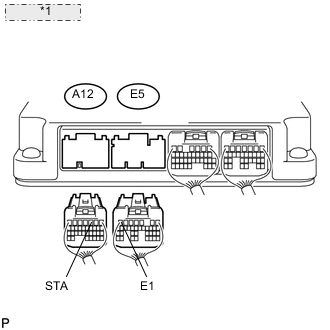
*1 TCM Connector Disconnect the A12 and E5 TCM connectors.
-
Measure the voltage of the wire harness side connectors.
Standard voltage Tester Connection Condition Specified Condition A12-3 (STA) - E5-7 (E1) Engine switch on (IG) and shift lever in P or N Below 2 V
NG 
REPAIR OR REPLACE HARNESS OR CONNECTOR (TCM - ST/IGCT RELAY)
OK
-
-
REPLACE TCM
-
Replace the TCM Click here.
NEXT
PERFORM AT REGISTRATION Click here
-
-
INSPECT PARK/NEUTRAL POSITION SWITCH
-
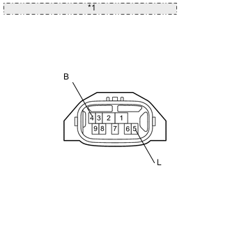
*1 Component without harness connected: (Park / Neutral Position Switch) Disconnect the E60 park/neutral position switch connector.
-
Measure the resistance of the park/neutral position switch when the shift lever is moved to each position.
Standard resistance Tester Connection Condition Specified Condition 4 (B) - 5 (L) Shift lever position P Below 1 Ω 4 (B) - 5 (L) Shift lever position N Below 1 Ω Result Result Proceed to NG A OK (for 1UR-FSE) B OK (for 1UR-FE) C
A
REPLACE PARK/NEUTRAL POSITION SWITCH Click here
B
CHECK CRANKING HOLDING FUNCTION CIRCUIT Click here
C
CHECK CRANKING HOLDING FUNCTION CIRCUIT Click here
-