FRONT DIFFERENTIAL CARRIER ASSEMBLY(for AWD) REASSEMBLY

PROCEDURE
-
INSTALL DIFFERENTIAL RING GEAR
-
Clean the differential ring gear set bolt hole.
-
Heat the differential ring gear to approximately 100°C (212°F) in boiling water.
CAUTION:
Use thick gloves to protect your hands as the differential ring gear is hot.
-
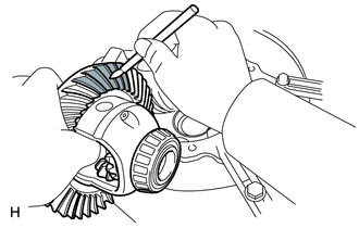
Carefully take the differential ring gear out of the boiling water.
-
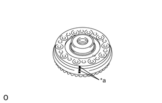
Text in Illustration *a Matchmark After the moisture on the differential ring gear has completely evaporated, quickly install the differential ring gear to the No. 1 front differential case sub-assembly.
Tech Tips
Align the matchmarks, differential case bolt holes and differential ring gear screw holes.
-
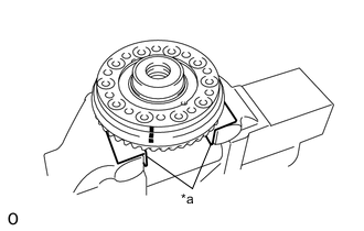
Text in Illustration *a Aluminum Plate Hold the No. 1 front differential case sub-assembly in a vise between aluminum plates.
Note
Do not overtighten the vise.
-
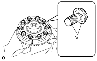
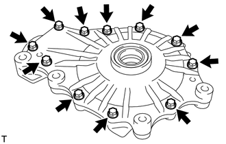
Apply adhesive to the threads and flanges of 10 new differential ring gear set bolts.
- Torque:
- 97 N*m { 984 kgf*cm, 71 ft.*lbf }
Adhesive Toyota Genuine Adhesive 1360K, Three Bond 1360K or equivalent Note
-
Tighten the bolts after the differential ring gear has sufficiently cooled down.
-
Install the differential case bolts by tightening diametrically opposite pairs uniformly in several passes.
-
-
INSTALL FRONT DRIVE PINION REAR TAPERED ROLLER BEARING OUTER RACE
-
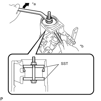
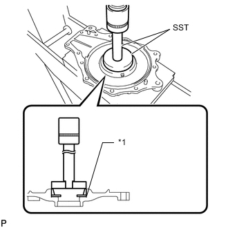
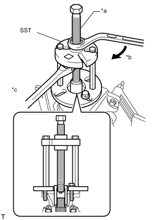
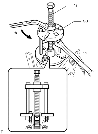
Text in Illustration *a Turn *b Hold Using SST, a bolt, nut, and washer, install the front drive pinion rear tapered roller bearing outer race to the differential carrier.
- SST
- 09950-60020 ( 09951-00730, 09951-00810 )
Note
Do not apply hypoid gear oil to a new bearing.
Tech Tips
If there are not enough threads, add another SST accordingly.
-
-
INSTALL FRONT DRIVE PINION FRONT TAPERED ROLLER BEARING OUTER RACE
-
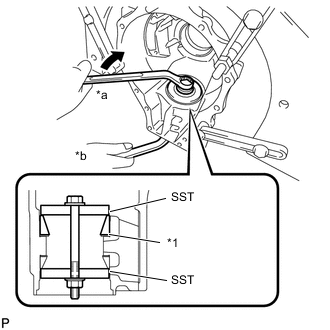
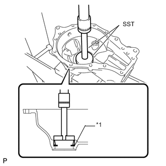
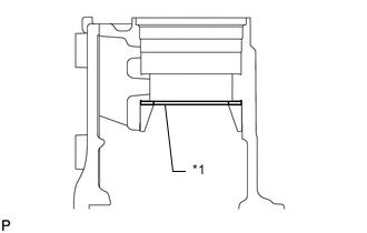
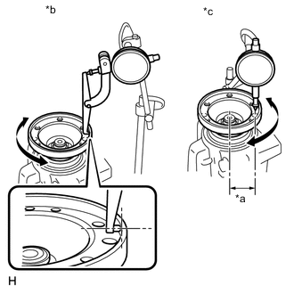
Text in Illustration *1 Front Drive Pinion Spacer Adjust Shim *a Turn *b Hold Install the front drive pinion spacer adjust shim to the differential carrier.
Tech Tips
Select a front drive pinion spacer adjust shim of the same thickness as the one removed.
-
Using SST, a bolt, nut, and washer, install the front drive pinion front tapered roller bearing outer race to the differential carrier.
- SST
- 09950-60020 ( 09951-00730, 09951-00810 )
Note
Do not apply hypoid gear oil to a new front drive pinion front tapered roller bearing.
-
-
INSTALL FRONT DRIVE PINION FRONT TAPERED ROLLER BEARING INNER RACE
-
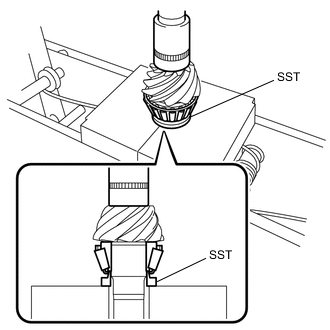
Using SST and a press, press in the front drive pinion front tapered roller bearing inner race to the drive pinion.
- SST
- 09309-14020
Note
Do not apply hypoid gear oil to a new front drive pinion front tapered roller bearing.
-
-
INSTALL FRONT DIFFERENTIAL CASE BEARING LH
-
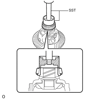
Using SST and a press, press the front differential case bearing LH (inner race) onto the No. 1 front differential case sub-assembly.
- SST
- 09710-30050
- 09950-70010 ( 09951-07100 )
Note
-
When installing a new front differential case bearing, do not apply Toyota genuine differential gear oil LT.
-
Be careful not to deform the front differential case bearing LH.
-
Align SST with the center of the front differential case.
-
When replacing a bearing, replace the front differential case bearing LH (inner race) and front differential case bearing LH (outer race) races as a set.
-
-
INSTALL FRONT DIFFERENTIAL CASE BEARING RH
-
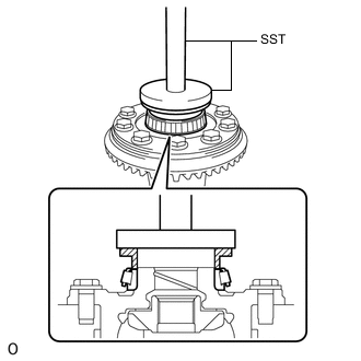
Using SST and a press, press a new front differential case bearing RH (inner race) onto the No. 1 front differential case sub-assembly.
- SST
- 09316-12010
- 09950-70010 ( 09951-07100 )
- 09951-00900
Note
-
When installing a new front differential case bearing, do not apply Toyota genuine differential gear oil LT.
-
Be careful not to deform the front differential case bearing RH.
-
Align SST with the center of the front differential case.
-
When replacing a bearing, replace the front differential case bearing RH (inner race) and front differential case bearing RH (outer race) races as a set.
-
-
INSTALL FRONT DIFFERENTIAL CASE BEARING LH
-
Remove the differential carrier from the overhaul attachment.
-
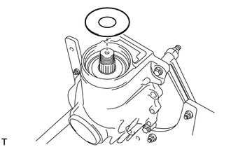
Install the differential case washer to the differential carrier.
Tech Tips
-
If the final gear set (drive pinion and ring gear) or front differential case bearing LH are replaced, select and install the thinnest differential case washer first.
-
If the drive pinion, ring gear or differential case are reused, select and install a differential case washer with the same thickness as the one before the disassembly first.
-
-
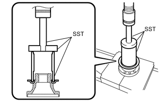
Text in Illustration *1 Differential Case Washer Using SST and a press, press in the front differential case bearing LH (outer race) to the differential carrier.
- SST
- 09950-60020 ( 09951-00790 )
- 09950-70010 ( 09951-07200 )
Note
-
When installing a new front differential case bearing, do not apply Toyota genuine differential gear oil LT.
-
When replacing a bearing, replace the front differential case bearing LH (inner race) and front differential case bearing LH (outer race) races as a set.
-
Press in the bearing and washer until they are fit against the end.
-
Do not place any load on the rolling contact surface of the bearing.
-
Install the front differential case oil seal LH after performing the teeth contact check and backlash adjustment.
-
-
INSTALL FRONT DIFFERENTIAL CASE BEARING RH
-
Install the differential case washer to the front differential carrier retainer sub-assembly.
Tech Tips
-
If the final gear set (drive pinion and ring gear) or front differential case bearing RH are replaced, select and install the thinnest differential case washer first.
-
If the drive pinion, ring gear or differential case are reused, select and install a differential case washer with the same thickness as the one before the disassembly first.
-
-
Text in Illustration *1 Differential Case Washer Using SST and a press, press in the front differential case bearing RH (outer race) to the front differential carrier retainer sub-assembly.
- SST
- 09950-60020 ( 09951-00890 )
- 09950-70010 ( 09951-07100 )
Note
-
When installing a new front differential case bearing, do not apply Toyota genuine differential gear oil LT.
-
When replacing a bearing, replace the front differential case bearing RH (inner race) and front differential case bearing RH (outer race) races as a set.
-
Press in the bearing and washer until they are fit against the end.
-
Do not place any load on the rolling contact surface of the bearing.
-
Install the front differential case oil seal RH after performing the teeth contact check and backlash adjustment.
-
-
INSTALL FRONT DIFFERENTIAL DUST DEFLECTOR
-
Using SST and a press, insert a new front differential dust deflector into the front drive pinion companion flange front sub-assembly.
- SST
- 09612-30012
- 09950-70010 ( 09951-07100 )
Note
-
Slowly press in the front differential dust deflector but not excessively.
-
If any burrs remain after pressing in the deflector, remove them.
-
-
ADJUST DRIVE PINION PRELOAD
-
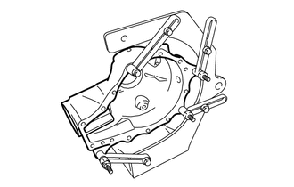
Fix the differential carrier with an attachment.
-
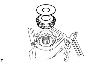
Install the differential drive pinion to the differential carrier, and then install the front drive pinion rear tapered roller bearing inner race and front differential drive pinion oil slinger while supporting the differential drive pinion by hand.
Note
-
Do not apply hypoid gear oil to a new bearing.
-
Do not drop the differential drive pinion.
Tech Tips
Install the front differential drive pinion bearing spacer and front differential carrier oil seal after performing the ring gear tooth contact pattern inspection adjustment.
-
-
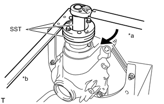
Text in Illustration *a Center Bolt *b Turn *c Hold Using SST, install the front drive pinion companion flange front sub-assembly.
- SST
- 09950-30012 ( 09951-03010, 09953-03010, 09954-03010, 09955-03030, 09956-03020 )
Note
-
As a front differential drive pinion bearing spacer is not installed, if SST is tightened excessively, SST, the front drive pinion companion flange front sub-assembly, and differential drive pinion will be damaged.
-
Support the differential drive pinion by hand until SST is installed.
-
Be careful not to drop the differential drive pinion.
Tech Tips
-
Before using SST center bolt, apply hypoid gear oil to its threads and tip.
-
Install the front drive pinion companion flange front sub-assembly so that there is some free play in the drive pinion.
-
Remove SST.
-
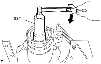
Text in Illustration *a Turn *b Hold Using SST and a torque wrench, tighten the flange nut little by little until it reaches the specified preload.
- SST
- 09213-58013
- 09330-00021
- 09229-55010
Maximum torque 490 N*m (4996 kgf*cm, 361 ft.*lbf) Note
-
Tighten the nut with a force of 100 N*m (1020 kgf*cm. 74 in.*lbf) while checking the starting torque of the differential drive pinion.
-
As the front differential drive pinion bearing spacer is not installed, tighten the flange nut little by little. Do not overtighten the nut.
-
Do not overtighten the nut, as the threads will become damaged.
-
Coat the threads the flange nut and differential drive pinion with hypoid gear oil LSD.
-
Perform the installment while supporting the overhaul attachment.
-
Using SST and a torque wrench, measure the preload.
- SST
- 09229-55010
Drive Pinion Preload (at starting) Bearing Standard New 3.9 to 4.6 N*m (40 to 46 kgf*cm, 35 to 41 in.*lbf) Reused 2.8 to 3.1 N*m (28 to 32 kgf*cm, 25 to 27 in.*lbf) Note
For a more accurate measurement, rotate the bearing forward and backward before the inspection.
Tech Tips
Record the preload for total preload measurement.
-
-
INSTALL NO. 1 FRONT DIFFERENTIAL CASE SUB-ASSEMBLY WITH RING GEAR
-
Remove the differential carrier from the overhaul attachment.
-
Install the No. 1 front differential case sub-assembly with ring gear to the differential carrier.
Note
Do not damage the 2 front differential case bearing and differential ring gear.
-
-
INSPECT AND ADJUST DIFFERENTIAL RING GEAR BACKLASH
-
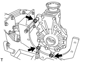
Install the front differential carrier retainer sub-assembly to the differential carrier with the 11 bolts.
- Torque:
- 58 N*m { 591 kgf*cm, 43 ft.*lbf }
-
Install the differential carrier to the overhaul attachment.
-
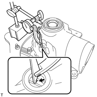
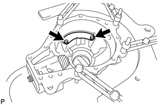
Connect a lever probe to a dial indicator. Insert the probe into the drain plug hole and set it onto the edge of one of the teeth of the ring gear at a right angle.
-
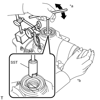
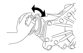
Text in Illustration *a Turn *b Hold Using SST, turn the differential case clockwise and counterclockwise and measure the ring gear backlash while holding the companion flange with your hand.
- SST
- 09564-50010
Standard backlash 0.15 to 0.23 mm (0.00591 to 0.00905 in.) Tech Tips
-
Measure at 3 or more areas around the circumference of the differential ring gear.
-
Record the measured value, as it is used to select the differential case washer.
-
If the result is outside of the standard range, replace the differential case washer with one of a different thickness in accordance with the following procedure.
-
Perform the tooth contact pattern inspection for the differential ring gear and differential drive pinion. The results will be used as a reference for selecting the differential case washer LH and RH.
-
Select a differential case washer from the table until the backlash measured value is in the standard range.
Differential Case Washer Thickness (LH) Thickness mm (in.) Thickness mm (in.) Thickness mm (in.) 2.11 to 2.13 (0.0831 to 0.0839) 2.43 to 2.45 (0.0957 to 0.0965) 2.75 to 2.77 (0.1083 to 0.1091) 2.13 to 2.15 (0.0839 to 0.0846) 2.45 to 2.47 (0.0965 to 0.0972) 2.77 to 2.79 (0.1091 to 0.1098) 2.15 to 2.17 (0.0846 to 0.0854) 2.47 to 2.49 (0.0972 to 0.0980) 2.79 to 2.81 (0.1098 to 0.1106) 2.17 to 2.19 (0.0854 to 0.0862) 2.49 to 2.51 (0.0980 to 0.0988) 2.81 to 2.83 (0.1106 to 0.1114) 2.19 to 2.21 (0.0862 to 0.0870) 2.51 to 2.53 (0.0988 to 0.0996) 2.83 to 2.85 (0.1114 to 0.1122) 2.21 to 2.23 (0.0870 to 0.0878) 2.53 to 2.55 (0.0996 to 0.1004) 2.85 to 2.87 (0.1122 to 0.1130) 2.23 to 2.25 (0.0878 to 0.0886) 2.55 to 2.57 (0.1004 to 0.1012) 2.87 to 2.89 (0.1130 to 0.1138) 2.25 to 2.27 (0.0886 to 0.0894) 2.57 to 2.59 (0.1012 to 0.1020) 2.89 to 2.91 (0.1138 to 0.1146) 2.27 to 2.29 (0.0894 to 0.0902) 2.59 to 2.61 (0.1020 to 0.1028) 2.91 to 2.93 (0.1146 to 0.1154) 2.29 to 2.31 (0.0902 to 0.0909) 2.61 to 2.63 (0.1028 to 0.1035) 2.93 to 2.95 (0.1154 to 0.1161) 2.31 to 2.33 (0.0909 to 0.0917) 2.63 to 2.65 (0.1035 to 0.1043) 2.95 to 2.97 (0.1161 to 0.1169) 2.33 to 2.35 (0.0917 to 0.0925) 2.65 to 2.67 (0.1043 to 0.1051) 2.97 to 2.99 (0.1169 to 0.1177) 2.35 to 2.37 (0.0925 to 0.0933) 2.67 to 2.69 (0.1051 to 0.1059) 2.99 to 3.01 (0.1177 to 0.1185) 2.37 to 2.39 (0.0933 to 0.0941) 2.69 to 2.71 (0.1059 to 0.1067) 3.01 to 3.03 (0.1185 to 0.1193) 2.39 to 2.41 (0.0941 to 0.0949) 2.71 to 2.73 (0.1067 to 0.1075) 3.03 to 3.05 (0.1193 to 0.1201) 2.41 to 2.43 (0.0949 to 0.0957) 2.73 to 2.75 (0.1075 to 0.1083) - Differential Case Washer Thickness (RH) Thickness mm (in.) Thickness mm (in.) Thickness mm (in.) 2.09 to 2.11 (0.0823 to 0.0831) 2.43 to 2.45 (0.0957 to 0.0965) 2.77 to 2.79 (0.1091 to 0.1098) 2.11 to 2.13 (0.0831 to 0.0839) 2.45 to 2.47 (0.0965 to 0.0972) 2.79 to 2.81 (0.1098 to 0.1106) 2.13 to 2.15 (0.0839 to 0.0846) 2.47 to 2.49 (0.0972 to 0.0980) 2.81 to 2.83 (0.1106 to 0.1114) 2.15 to 2.17 (0.0846 to 0.0854) 2.49 to 2.51 (0.0980 to 0.0988) 2.83 to 2.85 (0.1114 to 0.1122) 2.17 to 2.19 (0.0854 to 0.0862) 2.51 to 2.53 (0.0988 to 0.0996) 2.85 to 2.87 (0.1122 to 0.1130) 2.19 to 2.21 (0.0862 to 0.0870) 2.53 to 2.55 (0.0996 to 0.1004) 2.87 to 2.89 (0.1130 to 0.1138) 2.21 to 2.23 (0.0870 to 0.0878) 2.55 to 2.57 (0.1004 to 0.1012) 2.89 to 2.91 (0.1138 to 0.1146) 2.23 to 2.25 (0.0878 to 0.0886) 2.57 to 2.59 (0.1012 to 0.1020) 2.91 to 2.93 (0.1146 to 0.1154) 2.25 to 2.27 (0.0886 to 0.0894) 2.59 to 2.61 (0.1020 to 0.1028) 2.93 to 2.95 (0.1154 to 0.1161) 2.27 to 2.29 (0.0894 to 0.0902) 2.61 to 2.63 (0.1028 to 0.1035) 2.95 to 2.97 (0.1161 to 0.1169) 2.29 to 2.31 (0.0902 to 0.0909) 2.63 to 2.65 (0.1035 to 0.1043) 2.97 to 2.99 (0.1169 to 0.1177) 2.31 to 2.33 (0.0909 to 0.0917) 2.65 to 2.67 (0.1043 to 0.1051) 2.99 to 3.01 (0.1177 to 0.1185) 2.33 to 2.35 (0.0917 to 0.0925) 2.67 to 2.69 (0.1051 to 0.1059) 3.01 to 3.03 (0.1185 to 0.1193) 2.35 to 2.37 (0.0925 to 0.0933) 2.69 to 2.71 (0.1059 to 0.1067) 3.03 to 3.05 (0.1193 to 0.1201) 2.37 to 2.39 (0.0933 to 0.0941) 2.71 to 2.73 (0.1067 to 0.1075) 3.05 to 3.07 (0.1201 to 0.1209) 2.39 to 2.41 (0.0941 to 0.0949) 2.73 to 2.75 (0.1075 to 0.1083) - 2.41 to 2.43 (0.0949 to 0.0957) 2.75 to 2.77 (0.1083 to 0.1091) - Tech Tips
-
Make sure to increase the thickness of the LH and RH differential case washer by the same amount each time until the backlash is in the standard range.
-
Perform the tooth contact pattern inspection for the differential ring gear and differential drive pinion. The results will be used as a reference for selecting the differential case washer LH and RH.
-
When adjusting the backlash, adjust to within 0.18 mm (0.00709 in.) of the average of the measurements.
-
-
-
INSPECT AND ADJUST TOTAL PRELOAD
-
Using SST and a torque wrench, measure the preload with the teeth of the differential drive pinion and differential ring gear in contact.
- SST
- 09229-55010
Total Preload (at starting) Bearing Standard New 4.8 to 5.7 N*m (49 to 58 kgf*cm, 42 to 50 in.*lbf) Reused 3.3 to 3.9 N*m (34 to 40 kgf*cm, 30 to 35 in.*lbf) Tech Tips
-
When the value is outside the standard range, adjust using the differential case washer on the differential ring gear tooth side.
-
When the value is less than the lower limit of the standard range, replace the differential case washer with a thicker one.
-
When the value is more than the upper limit of the standard range, replace the differential case washer with a thinner one.
-
For reassembly purposes, record the measured value.
-
Connect a lever probe to a dial indicator. Insert the probe into the drain plug hole and set it onto the edge of one of the teeth of the differential ring gear at a right angle.
-

Text in Illustration *a Turn *b Hold Using SST, turn the differential case clockwise and counterclockwise and measure the differential ring gear backlash while holding the front drive pinion companion flange front sub-assembly with your hand.
- SST
- 09564-50010
Standard backlash 0.15 to 0.23 mm (0.00591 to 0.00905 in.) Tech Tips
-
Measure at 3 or more areas around the circumference of the differential ring gear.
-
If the backlash is not in the standard range, increase the LH and RH differential case washer by the same amount until the backlash is in the standard range.
-
Record the measured value and use it when selecting the differential case washer.
-
Perform the tooth contact pattern inspection for the differential ring gear and differential drive pinion. The results will be used as a reference for selecting the differential case washer LH and RH.
-
When adjusting the backlash, adjust to within 0.18 mm (0.00709 in.) of the average of the measurements.
-
Recheck the total preload.
-
-
INSPECT TOOTH CONTACT BETWEEN RING GEAR AND DRIVE PINION
-
Remove the differential carrier from the overhaul attachment.
-
Remove the 11 bolts and front differential carrier retainer sub-assembly from the differential carrier.
-
Remove the No. 1 front differential case sub-assembly with ring gear from the differential carrier.
Note
Do not damage the front differential case bearing and differential ring gear.
-
Uniformly apply a light coat of Prussian blue on both sides of 4 teeth on the differential ring gear.
-
Install the No. 1 front differential case sub-assembly with ring gear to the differential carrier.
Note
Do not damage the front differential case bearing and differential ring gear.
-
Install the front differential carrier retainer sub-assembly to the differential carrier with the 11 bolts.
- Torque:
- 58 N*m { 591 kgf*cm, 43 ft.*lbf }
-
Rotate the companion flange several times in the forward and backward rotation directions.
-
Remove the 11 bolts and front differential carrier retainer sub-assembly from the differential carrier.
-
Remove the No. 1 front differential case sub-assembly with ring gear from the differential carrier.
Note
Do not damage the front differential case bearing and differential ring gear.
-
Inspect the tooth contact pattern.

Text in Illustration *a Proper Contact *b Heel Contact *c Face Contact *d Select an adjusting washer that will shift the drive pinion closer to the ring gear (*b, *c) *e Toe Contact *f Flank Contact *g Select an adjusting washer that will shift the drive pinion away from to the ring gear (*e, *f) - - Tech Tips
The patterns indicated by the Prussian blue are the tooth contact locations.
Note
Check the tooth contact pattern at 4 or more positions around the circumference of the differential ring gear.
-
Text in Illustration *1 Front Drive Pinion Spacer Adjust Shim If the tooth contact is not proper, select a front drive pinion spacer adjust shim from the table and perform the tooth contact pattern inspection again.
Note
-
It is possible for the backlash to be adjusted within the standard range in instances of face contact and flank contact.
-
If the thickness of the front drive pinion spacer adjust shim changes, perform the backlash adjustment and inspect the total preload.
Front Drive Pinion Spacer Adjust Shim Thickness Thickness mm (in.) Thickness mm (in.) Thickness mm (in.) 0.99 to 1.01 (0.0354 to 0.0398) 1.17 to 1.19 (0.0461 to 0.0469) 1.35 to 1.37 (0.0531 to 0.0539) 1.01 to 1.03 (0.0398 to 0.0406) 1.19 to 1.21 (0.0469 to 0.0476) 1.37 to 1.39 (0.0539 to 0.0547) 1.03 to 1.05 (0.0406 to 0.0413) 1.21 to 1.23 (0.0476 to 0.0484) 1.39 to 1.41 (0.0547 to 0.0555) 1.05 to 1.07 (0.0413 to 0.0421) 1.23 to 1.25 (0.0484 to 0.0492) 1.41 to 1.43 (0.0555 to 0.0563) 1.07 to 1.09 (0.0421 to 0.0429) 1.25 to 1.27 (0.0492 to 0.0500) 1.43 to 1.45 (0.0563 to 0.0571) 1.09 to 1.11 (0.0429 to 0.0437) 1.27 to 1.29 (0.0500 to 0.0508) 1.45 to 1.47 (0.0571 to 0.0579) 1.11 to 1.13 (0.0437 to 0.0445) 1.29 to 1.31 (0.0508 to 0.0516) 1.47 to 1.49 (0.0579 to 0.0587) 1.13 to 1.15 (0.0445 to 0.0453) 1.31 to 1.33 (0.0516 to 0.0524) - 1.15 to 1.17 (0.0453 to 0.0461) 1.33 to 1.35 (0.0524 to 0.0531) - -
-
-
REMOVE DIFFERENTIAL CASE
-
Remove the 11 bolts and front differential carrier retainer sub-assembly from the differential carrier.
-
Remove the No. 1 front differential case sub-assembly with ring gear from the differential carrier.
Note
Do not damage the front differential case bearing and differential ring gear.
-
-
REMOVE FRONT DRIVE PINION COMPANION FLANGE FRONT NUT
-
Install the differential carrier to the overhaul attachment
-
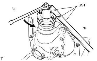
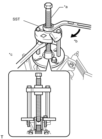
Text in Illustration *a Turn *b Hold Using SST to hold the flange, remove the front drive pinion companion flange front nut.
- SST
- 09213-58013
- 09330-00021
- 09229-55010
Note
Perform the removal while supporting the overhaul attachment.
-
-
REMOVE FRONT DRIVE PINION COMPANION FLANGE FRONT SUB-ASSEMBLY
-
Text in Illustration *a Center Bolt *b Turn *c Hold Using SST, remove the front drive pinion companion flange front sub-assembly from the differential carrier.
- SST
- 09950-30012 ( 09951-03010, 09953-03010, 09954-03010, 09955-03030, 09956-03020 )
Tech Tips
Before using SST center bolt, apply hypoid gear oil to its threads and tip.
-
-
REMOVE FRONT DIFFERENTIAL DRIVE PINION OIL SLINGER
-
Remove the front differential drive pinion oil slinger from the differential carrier.
-
-
REMOVE DIFFERENTIAL DRIVE PINION
-
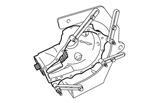
Remove the differential carrier together with the overhaul attachment from the engine stand.
-
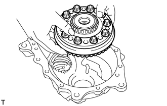
Set the differential carrier to an overhaul stand, etc. as shown in the illustration.
-
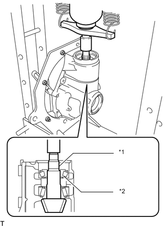
Text in Illustration *1 Differential Drive Pinion *2 Front Drive Pinion Rear Tapered Roller Bearing Inner Race Using a press, press out the differential drive pinion and front drive pinion rear tapered roller bearing inner race.
Note
Do not drop the differential drive pinion and front drive pinion rear tapered roller bearing inner race.
-
Install the differential carrier to the overhaul attachment as it was installed previously.
-
Install the differential carrier together with overhaul attachment to the engine stand.
-
-
INSTALL FRONT DIFFERENTIAL DRIVE PINION BEARING SPACER
-
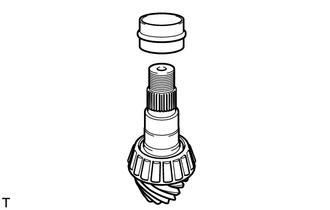
Install a new front differential drive pinion bearing spacer to the differential drive pinion.
-
-
INSTALL FRONT DRIVE PINION REAR TAPERED ROLLER BEARING INNER RACE
-
Text in Illustration *a Center Bolt *b Turn *c Hold Using SST and the front drive pinion companion flange front sub-assembly, press the front drive pinion rear tapered roller bearing inner race into the differential carrier.
- SST
- 09950-30012 ( 09951-03010, 09953-03010, 09954-03010, 09955-03040, 09956-03060 )
Note
-
As the differential drive pinion is supported by hand until SST is installed, be careful not to drop the differential drive pinion.
-
Apply grease to the threads and tip of SST center bolt before use.
-
Using SST, remove the front drive pinion companion flange front sub-assembly from the differential carrier.
Tech Tips
Before using SST center bolt, apply hypoid gear oil to its threads and tip.
-
-
INSTALL FRONT DIFFERENTIAL DRIVE PINION OIL SLINGER
-
Install the front differential drive pinion oil slinger to the differential carrier.
-
-
INSTALL FRONT DIFFERENTIAL CARRIER OIL SEAL
-
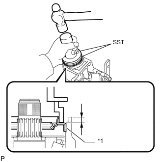
Text in Illustration *1 Front Differential Carrier Oil Seal Using SST and a hammer, tap in a new front differential carrier oil seal.
- SST
- 09309-36010
- 09502-24010
Standard depth 6.2 to 7.2 mm (0.244 to 0.283 in.) Note
-
Using a vernier caliper, measure the depth of the front differential carrier oil seal.
-
Measure at 3 or more areas around the circumference of the front differential carrier oil seal.
-
Make sure the difference between the maximum and minimum measured values is less than 0.75 mm (0.0295 in.), as a greater difference may lead to oil leaks.
-
Tap the front differential carrier oil seal uniformly so that the front differential carrier oil seal is straight.
-
Do not excessively tap the front differential carrier oil seal.
Tech Tips
First, uniformly tap in the front differential carrier oil seal until it is flush with the edge of the carrier, and then tap it little by little until the depth is within the standard range.
-
-
INSTALL FRONT DIFFERENTIAL BREATHER PLUG OIL DEFLECTOR
-
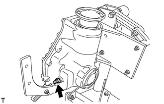
Install the front differential breather plug oil deflector to the differential carrier with the 2 bolts.
- Torque:
- 7.0 N*m { 71 kgf*cm, 62 in.*lbf }
-
-
INSTALL FRONT DRIVE PINION COMPANION FLANGE FRONT SUB-ASSEMBLY
-
Text in Illustration *a Center Bolt *b Turn *c Hold Using SST, install the front drive pinion companion flange front sub-assembly to the drive pinion.
- SST
- 09950-30012 ( 09951-03010, 09953-03010, 09954-03010, 09955-03040, 09956-03060 )
Note
Do not insert the front drive pinion companion flange front sub-assembly excessively as the preload will be adjusted in the following procedure.
Tech Tips
Before using SST center bolt, apply hypoid gear oil to its threads and tip.
-
-
INSPECT DRIVE PINION PRELOAD
-
Coat the threads of a new front drive pinion companion flange front nut with hypoid gear oil LSD.
-
Text in Illustration *a Turn *b Hold Using SST and a torque wrench, tighten the front drive pinion companion flange front nut while checking the preload.
- SST
- 09213-58013
- 09330-00021
- 09229-55010
Maximum torque 490 N*m (4996 kgf*cm, 361 ft.*lbf) Note
-
Tighten the front drive pinion companion flange front nut little by little to reach the specified preload, being careful not to exceed the maximum torque.
-
Do not overtighten the nut, as the threads will become damaged.
-
Measure the preload after rotating the front drive pinion companion flange front sub-assembly several times in the forward and backward directions to make sure the bearing is operating correctly.
-
Perform the installation while supporting the overhaul attachment.
-
Using SST and a torque wrench, measure the drive pinion preload.
- SST
- 09229-55010
Tech Tips
Record the drive pinion preload for the total preload inspection.
Drive Pinion Preload (at starting) Bearing Standard New 3.9 to 4.6 N*m (40 to 46 kgf*cm, 35 to 40 in.*lbf) Reused 2.8 to 3.1 N*m (28 to 32 kgf*cm, 25 to 27 in.*lbf) Note
The front differential drive pinion bearing spacer is made of plastic and changes shape when used. If the starting torque of the differential drive pinion is exceeded by mistake, make sure to replace the front differential drive pinion bearing spacer with a new one.
Tech Tips
-
If the preload is insufficient, tighten the nut 5 to 10° at a time until the preload is in the standard range.
-
If the tightening torque of the flange nut exceeds the specified torque but the preload is still insufficient, loosen the flange nut. Then check if the flange nut and drive pinion threads are damaged.
-
If there are no problems, replace the bearing spacer, apply hypoid gear oil LSD to the threads of the front drive pinion companion flange front nut and repeat the procedure above.
-
-
INSTALL NO. 1 FRONT DIFFERENTIAL CASE SUB-ASSEMBLY WITH RING GEAR
-
Remove the differential carrier from the overhaul attachment.
-
Install the No. 1 front differential case sub-assembly with ring gear to the differential carrier.
Note
Do not damage the front differential case bearing and differential ring gear.
-
-
INSTALL FRONT DIFFERENTIAL CARRIER RETAINER SUB-ASSEMBLY
-
Remove the seal packing attached on the differential carrier and front differential carrier retainer sub-assembly using a scraper and wire brush.
Note
Do not scratch the fitting surface.
-
Check that there is no foreign matter or damage on the installation surface of the front differential carrier retainer sub-assembly.
-
Apply seal packing to the front differential carrier retainer sub-assembly as shown in the illustration.
Seal packing Toyota Genuine Seal Packing 1281, Three bond 1281 or equivalent Note
-
Apply the seal packing in a continuous line, approximately 2 to 3 mm (0.0788 to 0.118 in.) in diameter.
-
Overlap the seal packing at least 10 mm (0.394 in.) at the beginning and the end of application.
-
Install the front differential carrier retainer sub-assembly within 3 minutes of application.
-
-
Install the front differential carrier retainer sub-assembly with the 11 bolts.
- Torque:
- 58 N*m { 591 kgf*cm, 43 ft.*lbf }
Note
Do not fill the oil or drive immediately after installing the front differential carrier retainer sub-assembly. Leave the vehicle for at least 1 hour. Also, avoid sudden acceleration and deceleration for at least 12 hours after application.
-
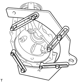
Set the differential carrier to an overhaul stand as shown in the illustration.
-
-
INSTALL FRONT DIFFERENTIAL BREATHER PLUG
-
Install the front differential breather plug to the differential carrier.
- Torque:
- 21 N*m { 214 kgf*cm, 15 ft.*lbf }
-
-
INSPECT TOTAL PRELOAD
-
Using SST and a torque wrench, measure the preload with the teeth of the differential drive pinion and differential ring gear in contact.
- SST
- 09229-55010
Total Preload (at starting) Bearing Standard New 4.8 to 5.7 N*m (49 to 58 kgf*cm, 42 to 50 in.*lbf) Reused 3.3 to 3.9 N*m (34 to 40 kgf*cm, 30 to 35 in.*lbf)
-
-
INSPECT DIFFERENTIAL RING GEAR BACKLASH
-
Connect a lever probe to a dial indicator. Insert the probe into the drain plug hole and set it onto the edge of one of the teeth of the differential ring gear at a right angle.
-

Text in Illustration *a Turn *b Hold Using SST, turn the differential case clockwise and counterclockwise and measure the differential ring gear backlash while holding the companion flange with your hand.
- SST
- 09564-50010
Standard backlash 0.15 to 0.23 mm (0.00591 to 0.00905 in.) Tech Tips
Measure at 3 or more areas around the circumference of the ring gear.
-
-
INSTALL FRONT DRIVE PINION COMPANION FLANGE FRONT SUB-ASSEMBLY
-
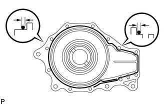
Text in Illustration *a 45.5 mm (1.79 in.) *b Vertical Runout *c Lateral Runout Wipe the inside surface of the companion flange with a cloth or equivalent and remove dirt and foreign matter.
-
Perform the vertical runout inspection.
-
Connect a lever probe to a dial indicator and set the probe at a right angle to the inner surface of the companion flange.
-
Measure the vertical runout of the companion flange.
Maximum runout 0.12 mm (0.00472 in.)
-
-
Perform the lateral runout inspection.
-
Set a dial indicator at a right angle to the surface of the companion flange as shown in the illustration.
-
Measure the lateral runout of the companion flange.
Maximum runout 0.08 mm (0.00315 in.)
-
-
-
STAKE FRONT DRIVE PINION COMPANION FLANGE FRONT NUT
-
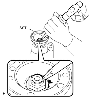
Using SST and a hammer, stake the front drive pinion companion flange front nut.
- SST
- 09930-00010
-
-
INSTALL FRONT DIFFERENTIAL CASE OIL SEAL
-
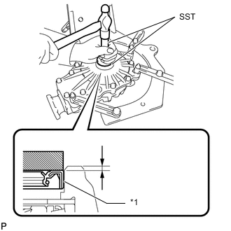
Text in Illustration *1 Front Differential Case Oil Seal LH for LH:
Using SST and a hammer, install a new front differential case oil seal LH.
- SST
- 09950-60010 ( 09951-00570 )
- 09950-70010 ( 09951-07100 )
Standard depth -0.5 to 0.5 mm (-0.0197 to 0.0196 in.) Note
-
Tap the front differential case oil seal uniformly so that the front differential case oil seal is straight.
-
Do not excessively tap the front differential case oil seal.
-
Make sure the difference between the maximum and minimum measured values is less than 0.57 mm (0.0224 in.), as a greater difference may lead to oil leaks.
-
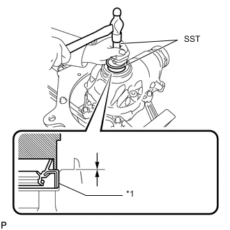
Text in Illustration *1 Front Differential Case Oil Seal RH for RH:
Using SST and a hammer, install a new front differential case oil seal RH.
- SST
- 09608-32010
- 09950-70010 ( 09951-07100 )
Standard depth 1.0 to 2.0 mm (0.0394 to 0.0787 in.) Note
-
Tap the front differential case oil seal uniformly so that the front differential case oil seal is straight.
-
Do not excessively tap the front differential case oil seal.
-
Make sure the difference between the maximum and minimum measured values is less than 0.47 mm (0.0185 in.), as a greater difference may lead to oil leaks.
-
-
INSTALL FRONT DIFFERENTIAL FILLER PLUG
Tech Tips
Perform this procedure as necessary.
-
Using a 10 mm socket hexagon wrench, install a new gasket and front differential filler plug to the front differential carrier assembly.
- Torque:
- 39 N*m { 398 kgf*cm, 29 ft.*lbf }
-
-
INSTALL FRONT DIFFERENTIAL DRAIN PLUG
Tech Tips
Perform this procedure as necessary.
-
Using a 10 mm socket hexagon wrench, install a new gasket and front differential drain plug to the front differential carrier assembly.
- Torque:
- 39 N*m { 398 kgf*cm, 29 ft.*lbf }
-
-
REMOVE FRONT DIFFERENTIAL CARRIER ASSEMBLY FROM OVERHAUL STAND
-
Remove the front differential carrier assembly from the overhaul attachment stand.
-