AUTOMATIC TRANSMISSION SYSTEM, Diagnostic DTC:P0776
| DTC Code | DTC Name |
|---|---|
| P0776 | Pressure Control Solenoid "B" Performance (Shift Solenoid Valve SL2) |
DESCRIPTION
Based on signals from the transmission speed sensors (NT, SP2 and NC3), the gear position is detected.
If the detected gear position is different than the commanded gear position, the TCM detects related mechanical problems in the shift solenoid valves, valve body and automatic transmission.
Tech Tips
Gear shift position when a problem occurs in shift solenoid valve SL2:
| TCM gear shift command | 1st | 2nd | 3rd | 4th | 5th | 6th | 7th | 8th |
| Actual gear position under SL2 stuck ON malfunction | 5th | 8th | 7th | 6th | 5th | 6th | 7th | 8th |
| Actual gear position under SL2 stuck OFF malfunction | 1st | 2nd | 3rd | 4th | N (1st)* | N* | N* | N* |
*: Neutral
| DTC Code | DTC Detection Condition
|
Trouble Area |
|---|---|---|
| P0776 |
|
|
| P0776 |
|
|
MONITOR DESCRIPTION
The TCM commands gear shifts by turning the shift solenoid valves on or off. According to the input shaft speed, intermediate (counter) shaft speed and output shaft speed, the TCM detects the actual gear position (1st, 2nd, 3rd, 4th, 5th, 6th, 7th or 8th gear position). When the gear position commanded by the TCM and the actual gear position are not the same, the TCM illuminates the MIL.
WIRING DIAGRAM
Refer to DTC P2765 Click here.
PROCEDURE
-
CHECK DTC OUTPUT (IN ADDITION TO DTC P0771, P0776 AND P2714)
-
Connect the intelligent tester to the DLC3.
-
Turn the engine switch on (IG).
-
Turn the intelligent tester on.
-
Enter the following menus: Powertrain / ECT / DTC.
-
Read the DTCs using the intelligent tester.
Result Display (DTC output) Proceed to Only P0771, P0776 and P2714 are output A Only P0776 is output B P0771, P0776, P2714, and other DTCs are output C Tech Tips
If any other codes besides P0771, P0776 and P2714 are output, perform troubleshooting for those DTCs first.
B 
INSPECT SHIFT SOLENOID VALVE SL2 Click here
C 
GO TO DTC CHART Click here
A 
-
-
CLEAR DTC AND PERFORM STALL SPEED TEST
-
Clear the DTCs Click here.
Tech Tips
Write down the currently output DTCs before clearing them.
-
Perform the stall speed test Click here.
Result Test Condition Proceed to Stall speed test can be performed A Stall speed test cannot be performed B
B
INSPECT SHIFT SOLENOID VALVE SLT Click here
A
-
-
CLEAR DTC AND PERFORM RUNNING TEST
-
Clear the DTCs Click here.
Tech Tips
Write down the currently output DTCs before clearing them.
-
Start the engine, drive the vehicle and perform the inspection.
Result Test Condition Proceed to
-
Transmission cannot be shifted between 1st gear and 4th gear
-
Transmission can only be shifted from 4th gear to 5th gear
-
Transmission cannot be shifted between 5th gear and 8th gear*
A
-
Transmission can be shifted from 1st gear to 4th gear
-
For 5th gear and above, transmission shifts to neutral
B Conditions other than those listed above C Tech Tips
*: If the transmission is shifted to 5th gear or above, gear shifts will no longer be able to be performed. When performing the test again, first clear the DTCs.
-
B
INSPECT SHIFT SOLENOID VALVE SL2 Click here
C
INSPECT SPEED SENSOR TERMINAL (NC3 TERMINAL) Click here
A
-
-
INSPECT SHIFT SOLENOID VALVE SR
-
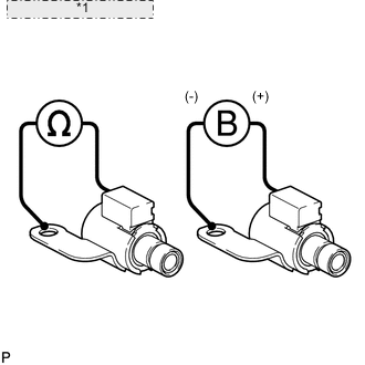
*1 Shift Solenoid Valve SR Remove shift solenoid valve SR Click here.
-
Measure the resistance according to the value(s) in the table below.
Standard Resistance Tester Connection Condition Specified Condition Shift solenoid SR connector - Shift solenoid SR body 20°C (68°F) 11 to 15 Ω -
Connect the battery's positive (+) lead to the terminal of the solenoid valve connector, and the negative (-) lead to the solenoid body. Then check that the valve moves and makes an operating noise.
OK Valve moves and makes operating noise.
NG
REPLACE SHIFT SOLENOID VALVE SR Click here
OK
INSPECT TRANSMISSION VALVE BODY ASSEMBLY Click here
-
-
INSPECT SHIFT SOLENOID VALVE SL2
-
Remove shift solenoid valve SL2 Click here.
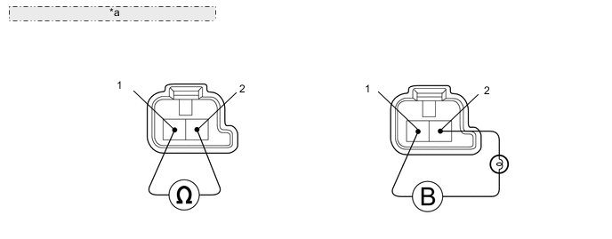
*a Component without harness connected: (Shift Solenoid Valve SL2) -
Measure the resistance according to the value(s) in the table below.
Standard Resistance Tester Connection Condition Specified Condition Terminal 1 of shift solenoid valve SL2 - Terminal 2 20°C (68°F) 5.0 to 5.6 Ω -
Connect the battery's positive (+) lead with a 21 W bulb to terminal 2 and the negative (-) lead to terminal 1 of the solenoid valve connector. Then check that the valve moves and makes an operating noise.
OK Valve moves and makes operating noise.
NG
REPLACE SHIFT SOLENOID VALVE SL2 Click here
OK
INSPECT TRANSMISSION VALVE BODY ASSEMBLY Click here
-
-
INSPECT SHIFT SOLENOID VALVE SLT
-
Remove shift solenoid valve SLT Click here.

*a Component without harness connected: (Shift Solenoid Valve SLT) -
Measure the resistance according to the value(s) in the table below.
Standard Resistance Tester Connection Condition Specified Condition Terminal 1 of shift solenoid valve SLT - Terminal 2 20°C (68°F) 5.0 to 5.6 Ω -
Connect the battery's positive (+) lead with a 21 W bulb to terminal 2 and the negative (-) lead to terminal 1 of the solenoid valve connector. Then check that the valve moves and makes an operating noise.
OK Valve moves and makes operating noise.
NG
REPLACE SHIFT SOLENOID VALVE SLT Click here
OK
-
-
INSPECT TRANSMISSION VALVE BODY ASSEMBLY
-
Check the transmission valve body assembly Click here.
OK There are no foreign objects on any valve.
NG
REPAIR OR REPLACE TRANSMISSION VALVE BODY ASSEMBLY Click here
OK
-
-
INSPECT TORQUE CONVERTER CLUTCH ASSEMBLY
-
Check the torque converter clutch assembly Click here.
OK The torque converter clutch operates normally.
OK
REPAIR OR REPLACE AUTOMATIC TRANSMISSION ASSEMBLY Click here
NG
REPLACE TORQUE CONVERTER CLUTCH ASSEMBLY Click here
-
-
INSPECT SPEED SENSOR TERMINAL (NC3 TERMINAL)
-
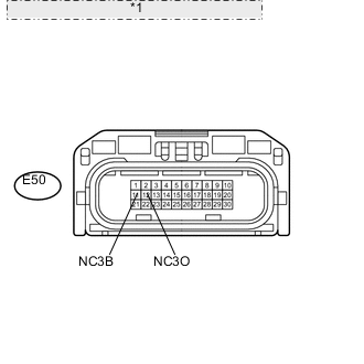
*1 Front view of wire harness connector: (to Transmission Wire) Disconnect the E50 transmission wire connector.
-
Turn the engine switch on (IG).
-
Measure the voltage according to the value(s) in the table below.
Standard Voltage Tester Connection Switch Condition Specified Condition E50-11 (NC3B) - Body ground Engine switch on (IG) 11 to 14 V -
Turn the engine switch off.
-
Measure the resistance according to the value(s) in the table below.
Standard Resistance Tester Connection Condition Specified Condition E50-12 (NC3O) - Body ground Always 100 Ω
NG
CHECK HARNESS AND CONNECTOR (TRANSMISSION WIRE - TCM) Click here
OK
-
-
INSPECT TRANSMISSION WIRE (SPEED SENSOR NC3)
-
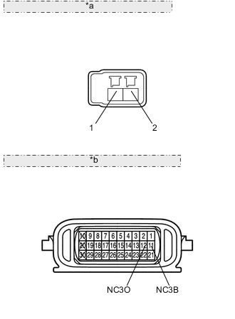
*a Front view of wire harness connector: (to Speed Sensor NC3) *b Component without harness connected: (Transmission Wire) Disconnect the speed sensor (NC3) connector.
-
Disconnect the E50 transmission wire connector.
-
Measure the resistance according to the value(s) in the table below.
Standard Resistance Tester Connection Condition Specified Condition Terminal 1 of the speed sensor (NC3) connector - 11 (NC3B) Always Below 1 Ω Terminal 2 of the speed sensor (NC3) connector - 12 (NC3O) Always Below 1 Ω Terminal 1 of the speed sensor (NC3) connector or 11 (NC3B) - Body ground Always 10 kΩ or higher Terminal 2 of the speed sensor (NC3) connector or 12 (NC3O) - Body ground Always 10 kΩ or higher
OK
REPLACE SPEED SENSOR Click here
NG
REPAIR OR REPLACE TRANSMISSION WIRE Click here
-
-
CHECK HARNESS AND CONNECTOR (TRANSMISSION WIRE - TCM)
-
Disconnect the E50 transmission wire connector.
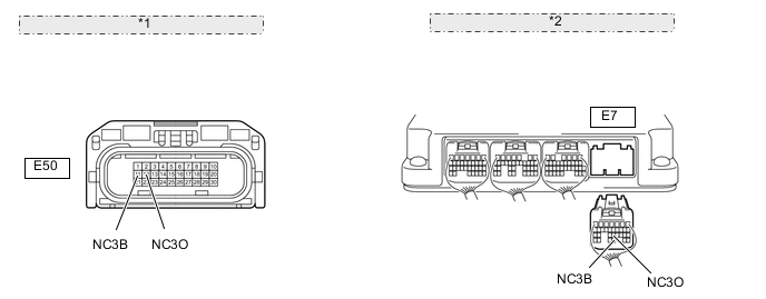
*1 Front view of wire harness connector: (to Transmission Wire) *2 Rear view of wire harness connector: (to TCM) -
Disconnect the E7 TCM connector.
-
Measure the resistance according to the value(s) in the table below.
Standard Resistance Tester Connection Condition Specified Condition E50-11 (NC3B) - E7-28 (NC3B) Always Below 1 Ω E50-12 (NC3O) - E7-22 (NC3O) Always Below 1 Ω E50-11 (NC3B) or E7-28 (NC3B) - Body ground Always 10 kΩ or higher E50-12 (NC3O) or E7-22 (NC3O) - Body ground Always 10 kΩ or higher
NG
REPAIR OR REPLACE HARNESS OR CONNECTOR
OK
-
-
REPLACE TCM
-
Replace the TCM Click here.
NEXT
PERFORM A/T CODE REGISTRATION Click here
-