DIFFERENTIAL CARRIER ASSEMBLY DISASSEMBLY

PROCEDURE
-
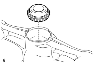
REMOVE REAR DIFFERENTIAL CARRIER COVER BREATHER PLUG
-
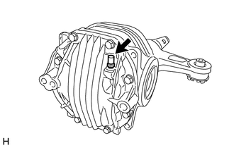
Remove the breather plug from the differential carrier cover.
-
-
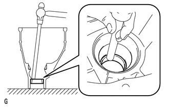
REMOVE REAR DIFFERENTIAL CARRIER COVER
-
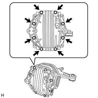
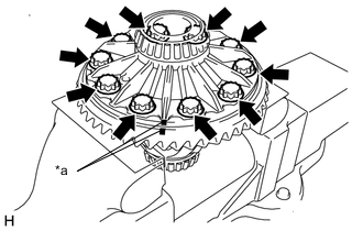
Remove the 8 bolts from the differential carrier cover.
-
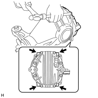
Using a brass bar and a hammer, remove the differential carrier cover from the differential carrier.
Note
-
Set the brass bar on the ribbed part of the differential carrier cover.
-
Do not damage the installation surface of the differential carrier.
-
-
-
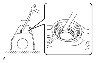
REMOVE REAR DIFFERENTIAL BREATHER PLUG OIL DEFLECTOR
-
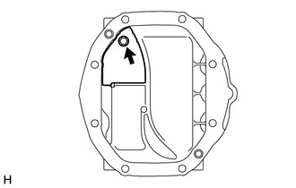
Remove the bolt and oil deflector from the differential carrier cover.
-
-
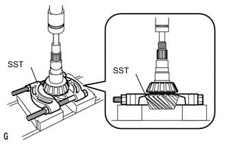
FIX DIFFERENTIAL CARRIER ASSEMBLY REAR
-
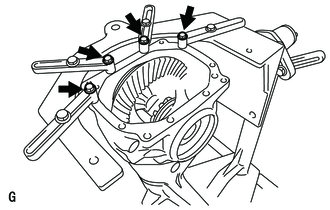
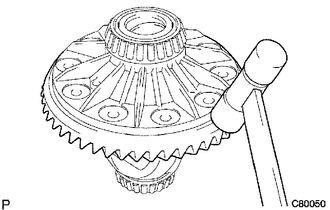
Set the differential carrier to an overhaul stand as shown in the illustration.
Tech Tips
Install the differential carrier to the back surface side of the ring gear as shown in the illustration.
-
-
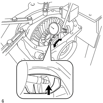
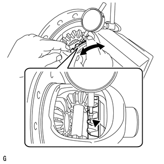
INSPECT DIFFERENTIAL RING GEAR RUNOUT
-
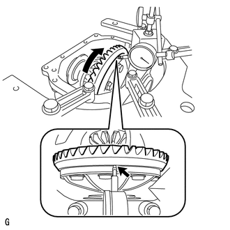
Place a dial indicator so that it is perpendicular to the back surface of the ring gear.
-
Rotate the ring gear and measure the ring gear runout.
Maximum runout 0.05 mm (0.0020 in.) If the runout exceeds the specified maximum value, remove the ring gear and check the runout of the differential case.
-
-
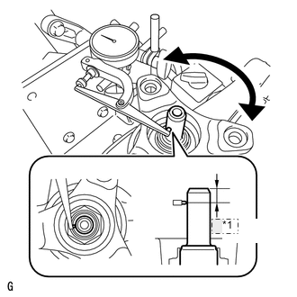
INSPECT DIFFERENTIAL RING GEAR BACKLASH
-
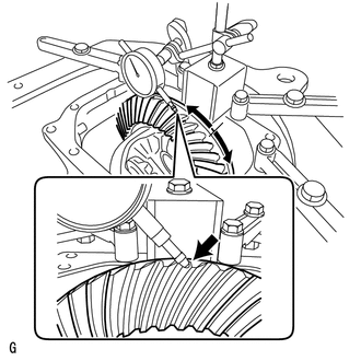
Place a dial indicator on the tip of the ring gear tooth at a right angle.
-
Fix the companion flange in place, and measure the ring gear backlash.
Standard backlash 0.08 to 0.13 mm (0.0031 to 0.0051 in.) Note
Measure the ring gear at 3 or more different places.
If the backlash is not within the specified range, adjust the backlash or repair as necessary.
-
-
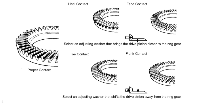
INSPECT TOOTH CONTACT BETWEEN RING GEAR AND DRIVE PINION
-
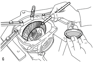
Uniformly apply a light coat of Prussian blue on both sides of 4 teeth on the differential ring gear.
-
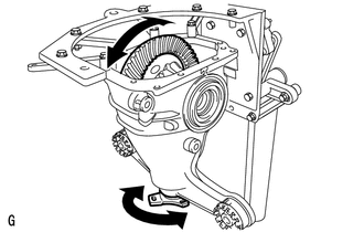
Rotate the companion flange several times in the forward and backward rotation directions.
-
Inspect the tooth contact pattern.
Note
Check the tooth contact pattern at 4 positions around the circumference of the ring gear.
Tech Tips
The patterns indicated by the Prussian blue are the tooth contact locations.
-
-
INSPECT DIFFERENTIAL SIDE GEAR BACKLASH
-
Place a dial indicator on the tip of the pinion gear tooth at a right angle.
-
Hold the side gear in the differential case and check that the backlash is 0 mm (0 in.). If not, replace the rear differential case with a new one.
If not, replace the rear differential case with a new one.
-
-
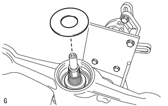
INSPECT RUNOUT OF DIFFERENTIAL DRIVE PINION
-
*1 10 mm Using a dial indicator, measure the runout of the drive pinion shaft at a position 10 mm (0.39 in.) from the end of the shaft.
Maximum runout 0.08 mm (0.0031 in.) If the runout is greater than the maximum, replace the drive pinion and ring gear.
-
-
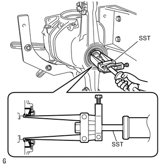
INSPECT DIFFERENTIAL DRIVE PINION PRELOAD
-
Using SST and a torque wrench, measure the drive pinion preload.
- SST
- 09229-55010
Standard drive pinion preload (at starting) 1.25 to 1.65 N*m (13 to 16 kgf*cm, 11 to 14 in.*lbf) If the preload is not within the specified range, adjust the rear differential drive pinion preload or replace the bearing spacer as necessary.
-
-
INSPECT TOTAL PRELOAD
-

Using SST and a torque wrench, measure the total preload.
- SST
- 09229-55010
Standard total preload (at starting) Item Specified Condition 2WD 1.74 to 2.96 N*m (18 to 30 kgf*cm, 16 to 26 in.*lbf) AWD 1.71 to 2.87 N*m (18 to 29 kgf*cm, 16 to 25 in.*lbf) If necessary, disassemble and inspect the differential.
-
-
REMOVE REAR DIFFERENTIAL SIDE GEAR SHAFT OIL SEAL
-
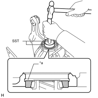
Using SST, tap the 2 oil seals.
- SST
- 09308-00010
-
-
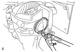
REMOVE REAR DIFFERENTIAL SIDE GEAR SHAFT SHAFT SNAP RING
-
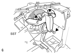
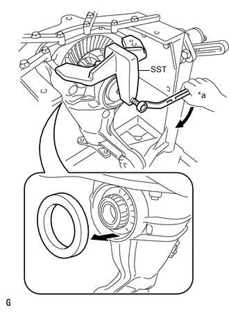
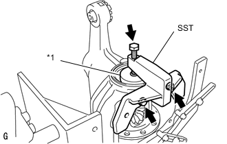
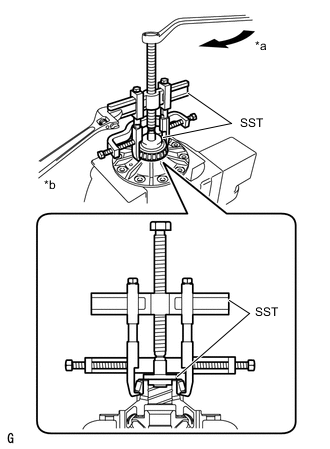
Text in Illustration *1 Disc Install the 2 bolts and SST to the differential carrier.
- SST
- 09571-50010
-
Tighten SST bolt until SST disc lightly touches the case bearing outer race.
-
Install a dial indicator to the rear differential carrier.
-
Tighten SST bolt and alter the differential carrier's shape to create a 0.1 mm (0.004 in.) clearance between the case bearing outer race and side gear shaft snap ring.
Note
Observe the dial indicator to ensure that the shape of the differential carrier does not change more than 0.2 mm (0.008 in.).
Tech Tips
-
For reassembly purposes, measure the thickness of the differential side gear shaft snap ring, and record the result.
-
Approximately 0.1 mm (0.004 in.) clearance between the case bearing outer race and the side gear shaft snap ring is sufficient for the washer to move slightly.
-
-
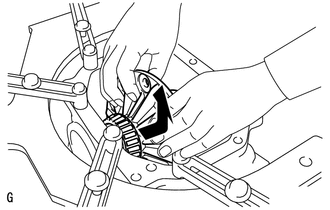
Using snap ring pliers, remove the side gear shaft snap ring on the ring gear tooth side.
Tech Tips
-
For reassembly purposes, measure the thickness of the differential side gear shaft snap ring, and record the result.
-
Place distinguishing marks on the left and right side differential side gear shaft snap rings to distinguish them (back surface side, tooth side). Then store them separately.
-
-
Remove the dial indicator from the differential carrier.
-
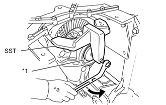
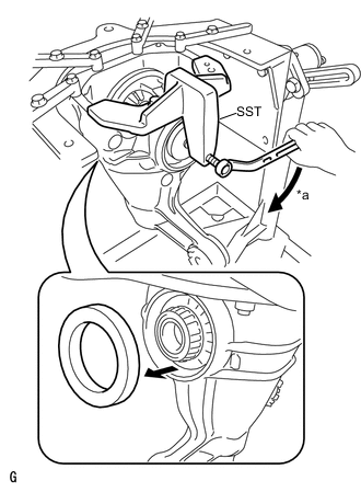
Text in Illustration *1 Disc *a Turn Loosen SST bolt until SST disc separates from the tooth side of the differential case bearing outer race.
Tech Tips
Do not remove SST.
-
-
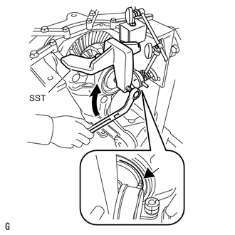
REMOVE REAR DIFFERENTIAL SIDE GEAR SHAFT SHAFT SNAP RING
-
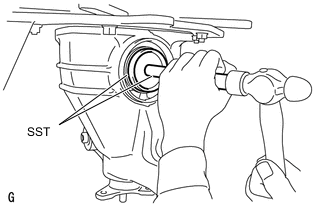
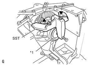
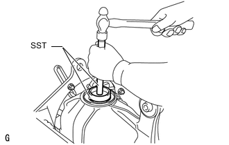
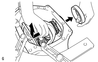
Using SST and a hammer, create a clearance between the case bearing outer race on the back surface of the ring gear and side gear shaft snap ring.
- SST
- 09608-32010
- 09950-70010 ( 09951-07200 )
Tech Tips
The clearance is not visible, but tapping SST with a hammer 3 or 4 times should be enough.
-
Using snap ring pliers, remove the side gear shaft snap ring on the back surface of the ring gear.
Tech Tips
-
l For reassembly purposes, measure the thickness of the differential side gear shaft snap ring, and record the result.
-
l Place distinguishing marks on the left and right side differential side gear shaft snap rings to distinguish them (back surface side, tooth side). Then store them separately.
-
-
-
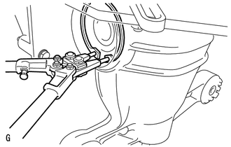
REMOVE REAR DIFFERENTIAL CASE BEARING
-
Text in Illustration *a Turn Tighten SST bolt and push out the case bearing outer race on the back surface of the ring gear.
- SST
- 09571-50010
Note
Do not drop the case bearing outer race.
Tech Tips
-
For reassembly purposes, mark the installation positions of the differential case bearing outer race and differential side gear shaft snap ring.
-
Place distinguishing marks on the left and right side differential case bearing outer races to distinguish them (back surface side, tooth side). Then store them separately.
-
Text in Illustration *1 Disc Remove the 2 bolts and SST from the differential carrier.
-
-
REMOVE REAR DIFFERENTIAL CASE BEARING
-
Raise the ring gear of the differential case slightly and remove the ring gear tooth side case bearing outer race.
Note
Do not drop the case bearing outer race.
Tech Tips
-
For reassembly purposes, mark the installation positions of the differential case bearing outer race and differential side gear shaft snap ring.
-
Place distinguishing marks on the left and right side differential case bearing outer races to distinguish them (back surface side, tooth side). Then store them separately.
-
-
-
REMOVE REAR DIFFERENTIAL CASE SUB-ASSEMBLY
-
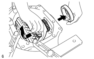
Pull out the differential case from the back surface side of the ring gear, and remove it from the differential carrier.
Note
Do not damage the case bearing.
-
-
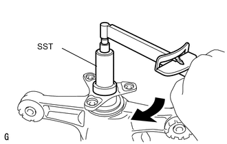
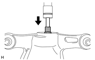
REMOVE REAR DRIVE PINION NUT
-
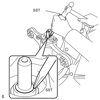
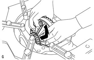
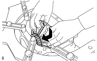
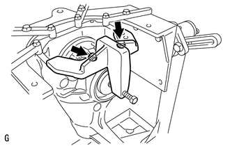
Using SST and a hammer, unstake the staked part of the drive pinion nut.
- SST
- 09930-00010
Note
-
Be sure to use SST with the tapered surface facing the shaft.
-
Do not grind the tip of SST with a grinder, etc.
-
Completely unstake the drive pinion nut to prevent damaging the threads of the drive pinion.
-
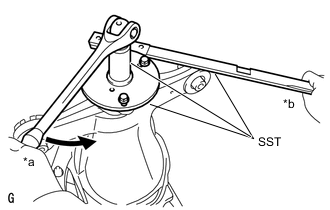
Text in Illustration *a Turn *b Hold Using SST, fix the companion flange in place.
- SST
- 09330-00021
- 09950-30012 ( 09955-03040 )
-
Perform the removal while supporting the overhaul attachment.
- SST
- 09229-55010
-
-
REMOVE REAR DRIVE PINION COMPANION FLANGE SUB-ASSEMBLY REAR
-
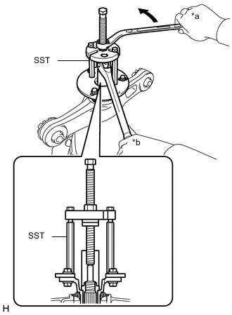
Text in Illustration *a Turn *b Hold Using SST, remove the companion flange.
- SST
- 09950-30012 ( 09951-03010, 09953-03010, 09954-03010, 09955-03040, 09956-03060 )
Note
Apply grease to the threads and tip of SST center bolt before use.
-
-
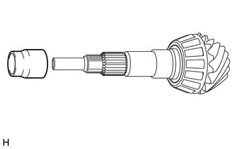
REMOVE REAR DIFFERENTIAL DUST DEFLECTOR
Tech Tips
Perform this procedure only when the dust deflector is damaged.
-
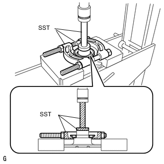
Using SST and a press, press out the dust deflector.
- SST
- 09950-00020
- 09950-60010 ( 09951-00440 )
- 09950-70010 ( 09951-07100 )
Note
-
Perform this procedure while tightening SST nut to secure the contact surfaces of SST and the dust deflector.
-
Do not drop the companion flange.
-
-
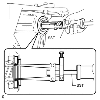
REMOVE REAR DIFFERENTIAL CARRIER OIL SEAL
-
Using SST, remove the oil seal from the differential carrier.
- SST
- 09308-00010
-
-
REMOVE REAR DIFFERENTIAL DRIVE PINION OIL SLINGER
-
Using a magnet hand, remove the oil slinger from the differential carrier.
-
-
REMOVE REAR DIFFERENTIAL CARRIER ASSEMBLY
-
Using a press, press out the drive pinion from the differential carrier.
Note
Do not drop the drive pinion.
-
-
REMOVE REAR DIFFERENTIAL DRIVE PINION BEARING SPACER
-
Remove drive pinion bearing spacer to the drive pinion.
-
-
REMOVE REAR DRIVE PINION FRONT TAPERED ROLLER BEARING
-
Remove the rear drive pinion front tapered roller bearing inner race from the differential carrier.
-
Using a brass bar and a hammer, tap out the rear drive pinion front tapered roller bearing outer race from the differential carrier.
-
-
REMOVE REAR DRIVE PINION REAR TAPERED ROLLER BEARING
-
Using SST and a press, press out the rear drive pinion rear tapered roller bearing inner race from the drive pinion.
- SST
- 09950-00020
Note
-
Perform this procedure while tightening SST nut to secure the contact surfaces of SST and the rear tapered roller bearing inner race.
-
Do not drop the drive pinion.
-
Using a brass bar and a hammer, tap out the rear drive pinion rear tapered roller bearing outer race and drive pinion washer from the differential carrier.
Note
Make sure to perform this procedure with the brass bar placed on the differential drive pinion washer. Do not damage the differential carrier assembly.
Tech Tips
For reassembly purposes, measure the thickness of the differential drive pinion washer, and record the result.
-
-
REMOVE DIFFERENTIAL RING GEAR
-
Text in Illustration *a AMatchmark Hold the differential case in a vise between aluminum plates.
Note
Do not overtighten the vise.
-
Put matchmarks on the ring gear and differential case.
-
Remove the 10 ring gear set bolts.
-
Using a plastic-faced hammer, tap on the ring gear to separate it from the differential case.
Tech Tips
Place a cloth on the tooth side of the ring gear to prevent damage.
-
-
INSPECT RUNOUT OF REAR DIFFERENTIAL CARRIER ASSEMBLY
Tech Tips
Only perform this procedure if the runout exceeded the maximum value during the inspection of the ring gear runout inspection.
-
Install the differential case to the differential carrier.
Note
Do not damage the case bearing.
-
Text in Illustration *a Groove Using SST and a hammer, tap in the case bearing outer race on the ring gear tooth side.
- SST
- 09608-32010
- 09950-70010 ( 09951-07200 )
Tech Tips
Tap in the case bearing outer race until half of the side gear shaft snap ring groove of the differential carrier can be seen.
-
Text in Illustration *1 Disc Install the 2 bolts and SST from the differential carrier.
- SST
- 09571-50010
-
Tighten SST bolt until SST disc lightly touches the case bearing outer race.
Tech Tips
Tighten SST bolt to apply preload to the differential case bearing.
-
Using SST and a hammer, tap in the case bearing outer race on the ring gear back surfaces side.
- SST
- 09608-32010
- 09950-70010 ( 09951-07200 )
Tech Tips
Tap in the case bearing outer race until it touches the case bearing inner race roller bearing.
-
Using snap ring pliers, remove the side gear shaft snap ring on the back surface of the ring gear.
-
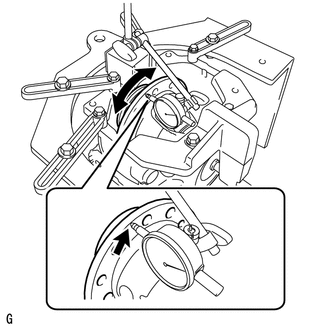
Place a dial indicator so that it is perpendicular to the differential case flange face.
-
Using a dial indicator, measure the differential case runout.
Maximum runout 0.05 mm (0.0020 in.) Tech Tips
Do not remove SST.
If the runout is greater than the maximum, replace the rear differential case with a new one.
-
Using snap ring pliers, remove the side gear shaft snap ring on the back surface of the ring gear.
-
Text in Illustration *a Turn Tighten SST bolt to push out the ring gear back surfaces side case bearing outer race.
- SST
- 09571-50010
Note
Do not drop the case bearing outer race.
-
Remove the 2 bolts and SST from the differential carrier.
-
Raise the ring gear side of the differential case slightly and remove the ring gear tooth side case bearing outer race.
-
Remove the differential case from the differential carrier.
Note
Do not damage the case bearing.
-
-
REMOVE REAR DIFFERENTIAL CASE BEARING
Tech Tips
Do not remove the rear differential case bearing unless replacing the differential case or differential case bearing.
-
Hold the differential case in a vise between aluminum plates.
Note
Do not overtighten the vise.
-
Text in Illustration *a Turn *1 Turn Using SST, remove the case bearing inner race LH and RH from the differential case.
- SST
- 09950-40011 ( 09951-04020, 09952-04010, 09953-04030, 09954-04010, 09955-04061, 09957-04010, 09958-04011 )
- 09950-60010 ( 09951-00350, 09951-00480, 09952-06010 )
Note
-
Do not deform the bearing cage if the bearing is to be reused.
-
Hook SST claw from the recess of the differential case to the bearing inner race.
-
Apply grease to the threads and tip of SST center bolt before use.
-
-
INSPECT DIFFERENTIAL SIDE GEAR BACKLASH
-
Hold the differential case in a vise between aluminum plates.
Note
Do not overtighten the vise.
-
Place a dial indicator on the tip of the pinion gear tooth at a right angle. Hold the side gear in the differential case and check that the backlash is 0 mm (0 in.).
If the backlash is not as specified, replace the rear differential case with a new one.
-