DIFFERENTIAL MOUNT CUSHION INSTALLATION

PROCEDURE
-
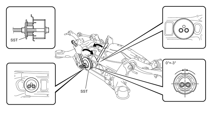
INSTALL REAR NO. 1 DIFFERENTIAL MOUNT CUSHION
-
Pass SST bolts through the area shown in the illustration, and install the mount cushion No. 1.
- SST
- 09570-24011
Note
-
Make sure the mount cushion installation angle misalignment is not over +-3
-
Make sure the mount cushion is not at an angle by first temporarily installing the mount cushion to the member before installing SST.
-
Before using SST bolts, apply hypoid gear oil to their threads.
-
Be sure to combine SST properly.
-
Confirm that SST contacts the entire seat surface of the mount cushion.
-
Do not install SST bolts at an angle.
-
Make sure SST bolts are tightened equally.
-
-
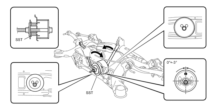
INSTALL REAR NO. 2 DIFFERENTIAL MOUNT CUSHION
-
Pass SST bolt through the area shown in the illustration, and install the mount cushion No. 2.
- SST
- 09570-24011
Note
-
Make sure the mount cushion installation angle misalignment is not over +-3.
-
Make sure the mount cushion is not at an angle by first temporarily installing the mount cushion to the member before installing SST.
-
Before using SST bolt, apply hypoid gear oil to their threads.
-
Be sure to combine SST properly.
-
Confirm that SST contacts the entire seat surface of the mount cushion.
-
Do not install SST bolts at an angle.
-
-
INSTALL REAR SUSPENSION MEMBER DAMPER
-
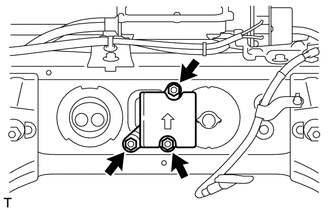
Install the rear suspension member damper with the 3 bolts.
- Torque:
- 25 N*m { 255 kgf*cm, 18 ft.*lbf }
-
-
INSTALL REAR SUSPENSION MEMBER SUB-ASSEMBLY
-
INSTALL REAR DIFFERENTIAL CARRIER ASSEMBLY WITH DRIVE SHAFT
-
Place the rear differential carrier assembly (with drive shaft) on a transmission jack.
CAUTION:
-
As the rear differential carrier assembly (with drive shaft) is very heavy, securely support it with the transmission jack.
-
Perform this procedure with several people supporting the rear differential carrier assembly (with drive shaft) so that it does not tilt or fall.
-
-
Slowly raise the transmission jack so that the rear differential carrier (with drive shaft) is at its installation position.
Note
When installing the rear differential carrier assembly (with drive shaft), do not damage the installation surface.
-
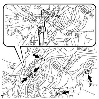
Temporarily install the mount stopper upper and lower with 2 new bolts (B).
-
Temporarily install 2 new bolts (A).
-
Temporarily install a new bolt (C).
-
Using SST and a 12 mm socket hexagon wrench, tighten the 2 bolts (A).
- SST
- 09249-63010
- Torque:
- without SST
- 103 N*m { 1050 kgf*cm, 76 ft.*lbf }
- with SST
- 75 N*m { 764 kgf*cm, 55 ft.*lbf }
Note
-
Use a torque wrench with a fulcrum length of 400 mm (16 in.). When using a torque wrench with a fulcrum length that is not 400 mm (16 in.), calculate the torque specification for the torque wrench and SST based on the "without SST" torque specification Click here.
-
Make sure SST and the wrench are connected in a straight line.
-
Tighten the bolts so that they do not interfere with the bolt holes of the mount cushions.
-
Using SST and a 12 mm socket hexagon wrench, tighten the bolt (C).
- SST
- 09249-63010
- Torque:
- without SST
- 103 N*m { 1050 kgf*cm, 76 ft.*lbf }
- with SST
- 75 N*m { 764 kgf*cm, 55 ft.*lbf }
Note
-
Use a torque wrench with a fulcrum length of 400 mm (16 in.). When using a torque wrench with a fulcrum length that is not 400 mm (16 in.), calculate the torque specification for the torque wrench and SST based on the "without SST" torque specification Click here.
-
Make sure SST and the wrench are connected in a straight line.
-
Tighten the bolts so that they do not interfere with the bolt holes of the mount cushions.
-
Tighten the 2 bolts (B).
- Torque:
- 105 N*m { 1071 kgf*cm, 77 ft.*lbf }
Note
Make sure that the mount stop upper and lower are not shifted or tilted.
-
-
INSTALL REAR AXLE ASSEMBLY LH
-
INSTALL REAR AXLE ASSEMBLY RH
Tech Tips
Use the same procedure described for the LH side.
-
INSTALL REAR SUSPENSION MEMBER BRACE LH
-
INSTALL REAR SUSPENSION MEMBER BRACE RH
-
INSTALL NO. 1 DIFFERENTIAL SUPPORT PROTECTOR
-
INSTALL NO. 2 DIFFERENTIAL SUPPORT PROTECTOR
-
INSTALL PROPELLER WITH CENTER BEARING SHAFT ASSEMBLY