GENERATOR DISASSEMBLY

PROCEDURE
-
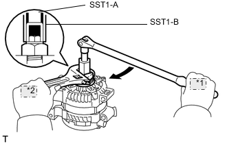
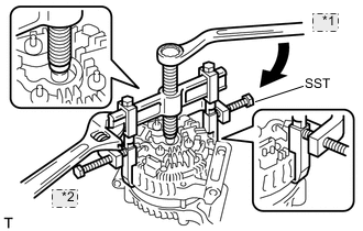
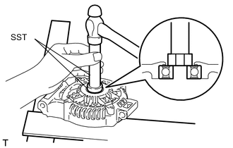
REMOVE GENERATOR PULLEY
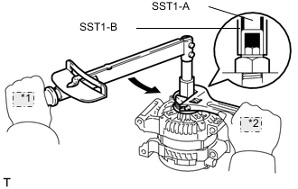
*1 Turn *2 Hold - SST
- 09820-63010 ( 09820-06010, 09820-06020 )
-
Install SST1-A to the pulley shaft.
-
Install SST1-B to SST1-A.
-
Hold SST 1-A on the pulley shaft area, and tighten SST 1-B to the specified torque.
- Torque:
- 39.2 N*m { 400 kgf*cm, 29 ft.*lbf }
Note
Securely fix SST1-A to the pulley shaft.
Tech Tips
Read SST1-B tightening torque by using the reactive torque of SST1-A.
-
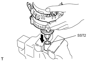
Mount 2 faces of SST2 in a vise.
-
With SST1-A and B attached to the generator, insert the pulley lock nut into the hexagon portion of SST2.
-
To loosen the pulley nut, rotate SST1-A in the generator's normal rotation direction.
Note
With SST2 (pulley nut) fixed in place, the pulley lock nut will loosen due to the rotation of SST1-A in the normal direction.
-
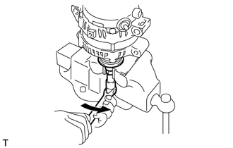
Remove the generator from SST2.
-
*1 Turn *2 Hold Fix SST1-B in place, and rotate SST1-A to the right to loosen it. Then remove SST1-A and B from the generator.
-
Remove the pulley lock nut and generator pulley.
-
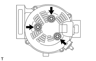
REMOVE GENERATOR REAR END COVER
-
Remove the 3 nuts and generator rear end cover from the generator coil.
-
-
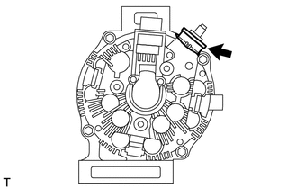
REMOVE GENERATOR TERMINAL INSULATOR
-
Remove the generator terminal insulator from the generator coil.
-
-
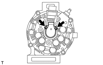
REMOVE GENERATOR BRUSH HOLDER ASSEMBLY
-
Remove the 2 screws and generator brush holder from the generator coil.
-
-
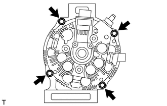
REMOVE GENERATOR COIL ASSEMBLY
-
Remove the 4 through bolts.
-
*1 Turn *2 Hold Using SST, remove the generator coil.
- SST
- 09950-40011 ( 09951-04020, 09952-04010, 09953-04020, 09954-04010, 09955-04071, 09957-04010, 09958-04011 )
-
-
REMOVE GENERATOR ROTOR ASSEMBLY
-
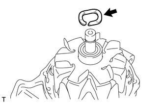
Remove the generator washer.
-
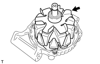
Remove the generator rotor from the drive end frame.
-
-
REMOVE GENERATOR ROTOR BEARING
-
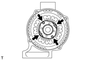
Remove the 4 screws, and remove the retainer from the drive end frame.
-
Using SST and a hammer, remove the generator rotor bearing from the drive end frame.
- SST
- 09950-60010 ( 09951-00270 )
- 09950-70010 ( 09951-07100 )
-