GENERATOR REASSEMBLY

PROCEDURE
-
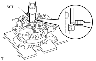
INSTALL GENERATOR ROTOR BEARING
-
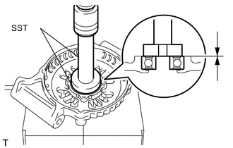
Using SST and a press, press a new generator rotor bearing into the drive end frame.
- SST
- 09950-60010 ( 09951-00500 )
- 09950-70010 ( 09951-07100 )
-
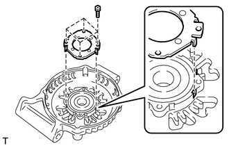
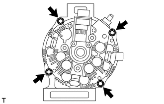
Align the protrusions of the retainer with the drive end frame's cutouts, and then install the retainer with the 4 screws.
- Torque:
- 3.0 N*m { 30 kgf*cm, 27 in.*lbf }
-
-
INSTALL GENERATOR ROTOR ASSEMBLY
-
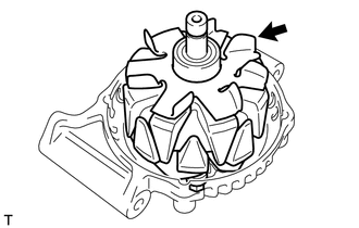
Install the generator rotor assembly.
-
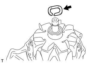
Install the generator washer.
-
-
INSTALL GENERATOR COIL ASSEMBLY
-
Using SST and a press, press the generator coil into the drive end frame.
- SST
- 09612-70100
-
Tighten the 4 through bolts.
- Torque:
- 5.8 N*m { 59 kgf*cm, 51 in.*lbf }
-
-
INSTALL GENERATOR BRUSH HOLDER ASSEMBLY
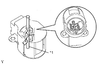
*1 Pin (diameter 1.0 mm)
-
*1 Pin (diameter 1.0 mm) Insert a pin (diameter 1.0 mm (0.039 in.)) into the generator brush holder assembly to fix the 2 brushes in place.
-
Install the generator brush holder to the generator coil with the 2 screws.
- Torque:
- 1.8 N*m { 18 kgf*cm, 16 in.*lbf }
-
Remove the pin (diameter 1.0 mm (0.039 in.)).
-
-
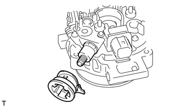
INSTALL GENERATOR TERMINAL INSULATOR
-
Install the generator terminal insulator to the generator coil.
-
-
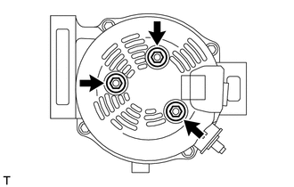
INSTALL GENERATOR REAR END COVER
-
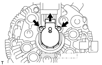
Install the generator rear end cover to the generator coil with the 3 nuts.
- Torque:
- 4.6 N*m { 47 kgf*cm, 41 in.*lbf }
-
-
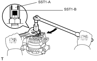
INSTALL GENERATOR PULLEY
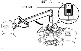
*1 Turn *2 Hold - SST
- 09820-63010 ( 09820-06010, 09820-06020 )
-
Install the generator pulley, and temporarily install the pulley lock nut.
-
Install SST1-A to the pulley shaft.
-
Install SST1-B to SST1-A.
-
Hold SST 1-A on the pulley shaft area, and tighten SST 1-B to the specified torque.
- Torque:
- 39.2 N*m { 400 kgf*cm, 29 ft.*lbf }
Note
Securely fix SST1-A to the pulley shaft.
Tech Tips
Read SST1-B tightening torque by using the reactive torque of SST1-A.
-
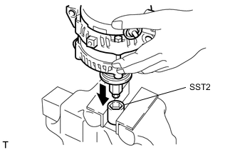
Mount 2 faces of SST2 in a vise.
-
With SST1-A and B attached to the generator, insert the pulley lock nut into the hexagon portion of SST2.
-
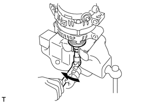
To tighten the pulley nut, rotate SST1-A in the generator's reverse rotation direction.
- Torque:
- 133 N*m { 1351 kgf*cm, 98 ft.*lbf }
-
Remove the generator from SST2.
-
*1 Turn *2 Hold Fix SST1-B in place, and rotate SST1-A to the right to loosen it. Then remove SST1-A and B from the generator.
-
Check that the pulley rotates smoothly.