EXHAUST PIPE INSTALLATION

CAUTION / NOTICE / HINT
CAUTION:
Perform the procedures below with at least 2 people.
PROCEDURE
-
INSTALL NO. 1 EXHAUST PIPE SUPPORT BRACKET SUB-ASSEMBLY (for 2WD)
-
Install the No. 1 exhaust pipe support bracket sub-assembly with the 2 bolts.
- Torque:
- 43 N*m { 438 kgf*cm, 32 ft.*lbf }
-
-
INSTALL EXHAUST PIPE DAMPER
-
Install the exhaust pipe damper to the tailpipe LH with 2 new bolts.
- Torque:
- 19 N*m { 194 kgf*cm, 14 ft.*lbf }
Note
Do not reuse the 2 removed bolts.
-
Install the exhaust pipe damper to the tailpipe RH with 2 new bolts.
- Torque:
- 19 N*m { 194 kgf*cm, 14 ft.*lbf }
Note
Do not reuse the 2 removed bolts.
-
-
INSTALL TAILPIPE RH
-
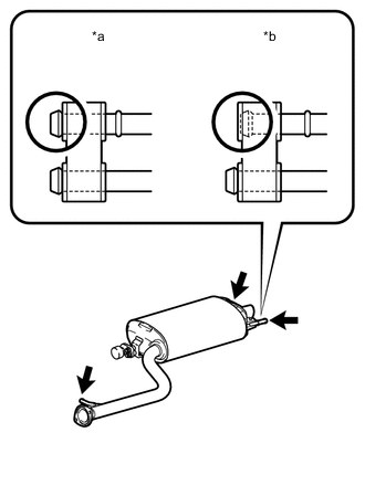
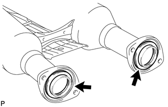
Text in Illustration *a CORRECT *b INCORRECT Connect the 3 exhaust pipe supports to install the tailpipe RH.
-
-
INSTALL TAILPIPE LH
-
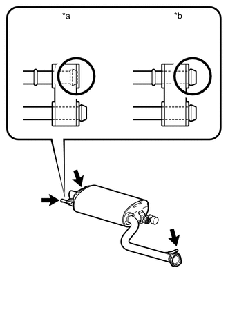
Text in Illustration *a INCORRECT *b CORRECT Connect the 3 exhaust pipe supports to install the tailpipe LH.
-
-
INSTALL HEATED OXYGEN SENSOR (for AWD)
Note
Do not strike the metal part of the heated oxygen sensor.
-
for Bank 1 Sensor 2:
Install the heated oxygen sensor to the front exhaust pipe assembly by hand.
-
for Bank 1 Sensor 2:
-
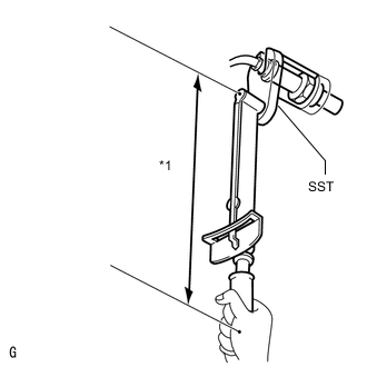
Text in Illustration *1 Fulcrum Length Using SST, tighten the heated oxygen sensor.
- SST
- 09224-00010
- Torque:
- without SST
- 44 N*m { 449 kgf*cm, 32 ft.*lbf }
- with SST
- 40 N*m { 408 kgf*cm, 30 ft.*lbf }
Tech Tips
-
Use a torque wrench with a fulcrum length of 300 mm (11.8 in.). When using a torque wrench with a fulcrum length that is not 300 mm (11.8 in.), calculate the torque specification for the torque wrench and SST based on the "without SST" torque specification Click here.
-
Make sure SST and the torque wrench are connected in a straight line.
-
-
INSTALL FRONT EXHAUST PIPE ASSEMBLY
-
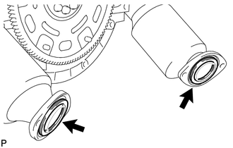
Install 2 new gaskets to the exhaust manifold LH and exhaust manifold RH.
Note
Do not reuse the 2 removed gaskets.
-
Install 2 new gaskets to the front exhaust pipe rear ends.
-
Install the front exhaust pipe assembly to the exhaust manifold LH and exhaust manifold RH with the 4 bolts and 4 new nuts.
- Torque:
- 39 N*m { 398 kgf*cm, 29 ft.*lbf }
Note
Do not reuse the 4 removed nuts.
Tech Tips
-
During installation, hold the front exhaust pipe assembly.
-
Hold the bolt and then tighten the nut with the specified torque.
-
Install the front exhaust pipe assembly to the tailpipe LH and tailpipe RH with the 4 bolts.
- Torque:
- 39 N*m { 398 kgf*cm, 29 ft.*lbf }
Tech Tips
During installation, hold the front exhaust pipe assembly.
-
-
CONNECT HEATED OXYGEN SENSOR (for 2WD)
Note
Do not strike the metal part of the heated oxygen sensor.
-
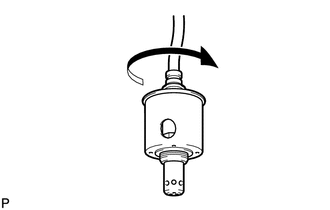
Rotate the heated oxygen sensors counterclockwise the same number of times as recorded in the removal procedure, and install then to the front exhaust pipe assembly by hand.
Note
After rotating the heated oxygen sensor counterclockwise the same number of times as the removal procedure, install it while making sure that the wire harness is not twisted.
-
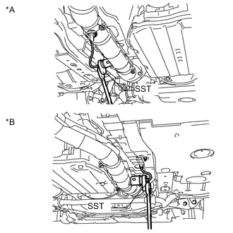
Using SST, tighten the 2 heated oxygen sensors.
- SST
- 09224-00010
- Torque:
- without SST
- 44 N*m { 449 kgf*cm, 32 ft.*lbf }
- with SST
- 40 N*m { 408 kgf*cm, 30 ft.*lbf }
Text in Illustration *A for Bank 1 Sensor 2 *B for Bank 2 Sensor 2 Tech Tips
-
Use a torque wrench with a fulcrum length of 300 mm (11.8 in.). When using a torque wrench with a fulcrum length that is not 300 mm (11.8 in.), calculate the torque specification for the torque wrench and SST based on the "without SST" torque specification Click here.
-
Make sure SST and the torque wrench are connected in a straight line.
Text in Illustration *1 Fulcrum Length -
Connect the 2 grommets to the floor panel.
-
-
CONNECT HEATED OXYGEN SENSOR (for AWD)
-
Connect the heated oxygen sensor connector.
-
Rotate the heated oxygen sensor counterclockwise the same number of times as recorded in the removal procedure, and install it to the front exhaust pipe assembly by hand.
Note
After rotating the heated oxygen sensor counterclockwise the same number of times as the removal procedure, install it while making sure that the wire harness is not twisted.
-
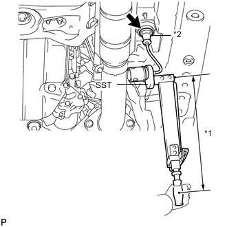
Text in Illustration *1 Fulcrum Length *2 Grommet Using SST, tighten the heated oxygen sensor.
- SST
- 09224-00010
- Torque:
- without SST
- 44 N*m { 449 kgf*cm, 32 ft.*lbf }
- with SST
- 40 N*m { 408 kgf*cm, 30 ft.*lbf }
Tech Tips
-
Use a torque wrench with a fulcrum length of 300 mm (11.8 in.). When using a torque wrench with a fulcrum length that is not 300 mm (11.8 in.), calculate the torque specification for the torque wrench and SST based on the "without SST" torque specification Click here.
-
Make sure SST and the torque wrench are connected in a straight line.
-
Connect the grommet to the floor panel.
-
-
INSPECT FOR EXHAUST GAS LEAK
-
If gas is leaking, tighten the areas necessary to stop the leak. Replace the damaged parts as necessary.
-
-
INSTALL FRONT CENTER FLOOR BRACE SUB-ASSEMBLY
-
Push in the 2 clips in the upward direction of the vehicle and install the front center floor brace sub-assembly with the 8 bolts.
- Torque:
- 7.4 N*m { 75 kgf*cm, 65 in.*lbf }
-
-
INSTALL FRONT CENTER FLOOR COVER (for AWD)
-
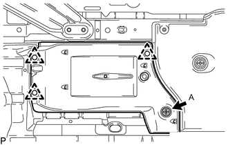
INSTALL FRONT FLOOR COVER RH (for 2WD)
-
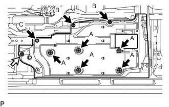
Push in the 5 clips labeled A in the illustration in the upward direction of the vehicle to install the front floor cover RH.
Text in Illustration 
Bolt 
Nut 
Screw -
Tighten the 2 clips labeled B in the illustration.
-
Install the clip labeled C and the nut.
- Torque:
- 5.4 N*m { 55 kgf*cm, 48 in.*lbf }
-
Install the front floor service hole cover with the 4 clips.
-
-
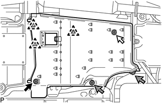
INSTALL FRONT FLOOR COVER RH (for AWD)
-
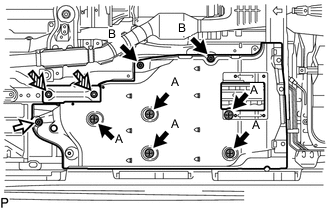
Push in the 5 clips labeled A in the illustration in the upward direction of the vehicle to install the front floor cover RH.
Text in Illustration Clip Nut Bolt -
Tighten the 2 clips labeled B in the illustration.
-
Install the 2 bolts and nut.
- Torque:
- 5.4 N*m { 55 kgf*cm, 48 in.*lbf }
-
Install the front floor service hole cover with the 4 clips.
-
-
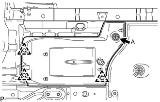
INSTALL FRONT FLOOR COVER LH (for 2WD)
-
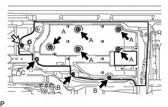
Push in the 5 clips labeled A in the illustration in the upward direction of the vehicle to install the front floor cover LH.
Text in Illustration Clip Nut -
Tighten the 2 clips labeled B in the illustration.
-
Install the clip labeled C and the nut.
- Torque:
- 5.4 N*m { 55 kgf*cm, 48 in.*lbf }
-
Install the front floor service hole cover with the 4 clips.
-
-
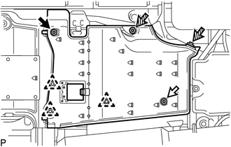
INSTALL FRONT FLOOR COVER LH (for AWD)
-
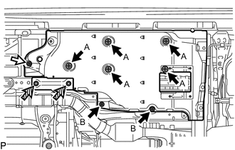
Push in the 5 clips labeled A in the illustration in the upward direction of the vehicle to install the front floor cover LH.
Text in Illustration Clip Nut Bolt -
Tighten the 2 clips labeled B in the illustration.
-
Install the 2 bolts and nut.
- Torque:
- 5.4 N*m { 55 kgf*cm, 48 in.*lbf }
-
Install the front floor service hole cover with the 4 clips.
-
-
INSTALL FRONT FENDER MAIN SEAL RH
-
Push in the clip labeled A in the illustration in the upward direction of the vehicle and install the front fender main seal RH with the 3 clips.
-
-
INSTALL FRONT FENDER MAIN SEAL LH
-
Push in the clip labeled A in the illustration in the upward direction of the vehicle and install the front fender main seal LH with the 3 clips.
-
-
INSTALL REAR FLOOR SIDE MEMBER COVER RH
-
Install the rear floor side member cover RH with the 3 clips, 2 screws, nut and bolt.
- Torque:
- 5.4 N*m { 55 kgf*cm, 48 in.*lbf }
Text in Illustration Bolt Nut Screw
-
-
INSTALL REAR FLOOR SIDE MEMBER COVER LH
-
Install the rear floor side member cover LH with the 3 clips, 2 screws, nut and bolt.
- Torque:
- 5.4 N*m { 55 kgf*cm, 48 in.*lbf }
Text in Illustration Bolt Nut Screw
-
-
INSTALL NO. 6 ROCKER PANEL MOULDING PROTECTOR
-
Install the No. 6 rocker panel moulding protector with the 2 clips and screw.
-
-
INSTALL NO. 5 ROCKER PANEL MOULDING PROTECTOR
-
Install the No. 5 rocker panel moulding protector with the 2 clips and screw.
-
-
INSTALL NO. 1 DIFFERENTIAL SUPPORT PROTECTOR
-
INSTALL NO. 2 DIFFERENTIAL SUPPORT PROTECTOR