CYLINDER HEAD REASSEMBLY

CAUTION / NOTICE / HINT
Note
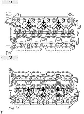
There are two cylinder head assembly shapes. Valve spring type A can only be used with cylinder head type A and valve spring type B can only be used with cylinder head type B. The combination cannot be changed.
Tech Tips
-
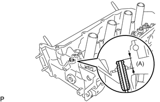
The standard protrusion amount (A) of the valve guide bush determines whether the cylinder head is type A or B.
Standard Protrusion Height (A) Type Specified Condition Cylinder Head Type A 14.3 to 14.7 mm (0.563 to 0.579 in.) Cylinder Head Type B 15.8 to 16.2 mm (0.622 to 0.638 in.) -
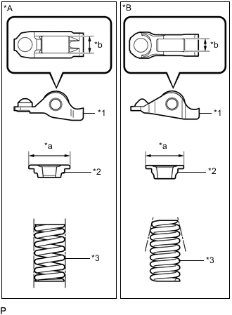
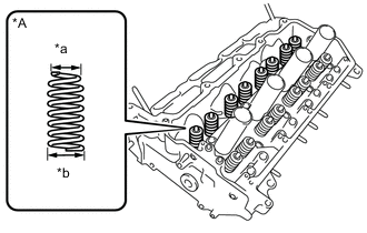
*A Valve Spring Type A *B Valve Spring Type B *1 No. 1 Valve Rocker Arm Sub-assembly *2 Valve Spring Retainer *3 Inner Compression Spring *a Valve Spring Retainer Outer Diameter *b No. 1 Valve Rocker Arm Roller Width The shape of the inner compression spring determines whether the valve spring type is A or B.
-
The No. 1 valve rocker arm, inner compression spring and valve spring retainer have two different shapes and are not interchangeable.
Valve Spring Type No. 1 Valve Rocker Arm Roller Width Valve Spring Retainer Outer Diameter Inner Compression Spring Shape A 10.7 mm (0.421 in.) 23.4 mm (0.921 in.) Straight B 8.0 mm (0.315 in.) 18.9 mm (0.744 in.) Taper
PROCEDURE
-
REPLACE STUD BOLT
Note
If a stud bolt is deformed or threads are damaged, replace it.
-
Using E6 and E8 "TORX" socket wrenches, install the stud bolts.
- Torque:
- 9.0 N*m { 92 kgf*cm, 80 in.*lbf }
- for stud bolts A, B, C and D
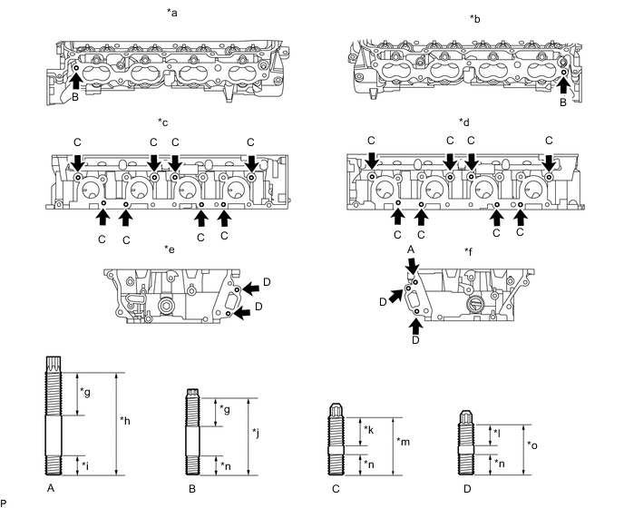
Text in Illustration *a for Bank 2 Intake Side *b for Bank 1 Intake Side *c for Bank 2 Exhaust Side *d for Bank 1 Exhaust Side *e for Bank 2 Front Side *f for Bank 1 Front Side *g 24 mm (0.945 in.) *h 52 mm (2.05 in.) *i 12 mm (0.472 in.) *j 45 mm (1.77 in.) *k 20 mm (0.787 in.) *l 14 mm (0.551 in.) *m 35 mm (1.38 in.) *n 13 mm (0.512 in.) *o 29 mm (1.14 in.) - -
-
-
INSTALL NO. 2 STRAIGHT SCREW PLUG
-
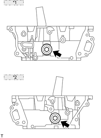
*1 for Bank 2: *2 for Bank 1: Using a 14 mm hexagon wrench, install 2 new gaskets and the 2 straight screw plugs.
- Torque:
- 85 N*m { 867 kgf*cm, 63 ft.*lbf }
-
-
INSTALL NO. 1 STRAIGHT SCREW PLUG
-
*1 for Bank 2: *2 for Bank 1: Using a 10 mm hexagon wrench, install 6 new gaskets and the 6 straight screw plugs.
- Torque:
- 44 N*m { 449 kgf*cm, 32 ft.*lbf }
-
-
INSTALL VALVE SPRING SEAT
-
Install the valve spring seats to the cylinder head.
-
-
INSTALL VALVE STEM OIL SEAL
-
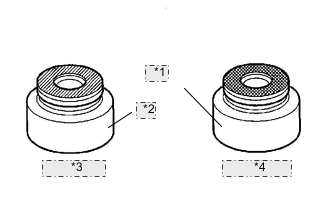
*1 Gray *2 Brown *3 Intake Side *4 Exhaust Side Apply a light coat of engine oil to new oil seals.
Note
Pay attention when installing the intake and exhaust oil seals. For example, installing the intake oil seal into the exhaust side or installing the exhaust oil seal to the intake side can cause installation problems later.
Tech Tips
The intake valve oil seals are gray and the exhaust valve oil seals are black.
-
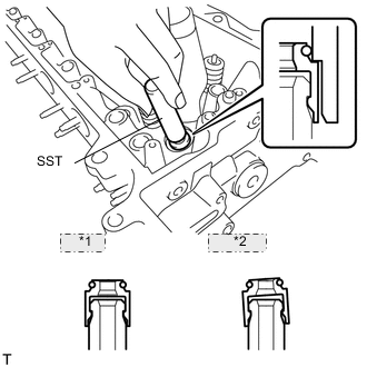
*1 CORRECT *2 INCORRECT Using SST, push in the oil seals.
- SST
- 09201-41020
Note
Failure to use SST will cause the seal to be damaged or improperly seated.
-
-
INSTALL INTAKE VALVE
Tech Tips
The shape of the inner compression spring determines whether the valve spring type described here is A or B.
-
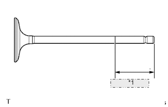
*1 40 mm or more Apply plenty of engine oil to the tip area of the intake valve shown in the illustration.
-
*A Valve Spring Type B *a Narrow *b Wide Install the valve, compression spring and spring retainer to the cylinder head.
Note
-
Install the same parts in the same combination to their original locations.
-
Valve Spring Type B:
Install the inner compression spring to the wide end of the cylinder head sub-assembly.
-
-
Valve Spring Type A:
-
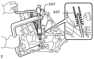
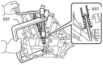
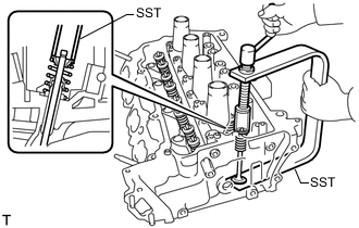
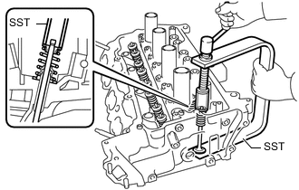
Using SST and wooden blocks, compress the spring and install the retainer lock.
- SST
- 09202-70020 ( 09202-00010, 09202-01010, 09202-01020 )
-
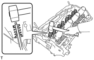
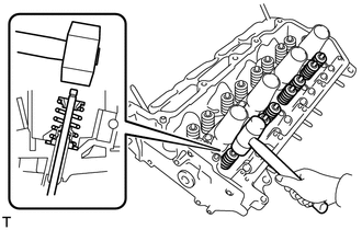
Using a plastic-faced hammer, lightly tap the valve stem tip to ensure a proper fit.
Note
-
Do not damage the valve stem tip.
-
Be careful not to damage the retainer.
-
-
-
Valve Spring Type B:
-
Using SST and wooden blocks, compress the spring and install the retainer lock.
- SST
- 09202-70020 ( 09202-01010, 09202-01020 )
- 09202-00021
-
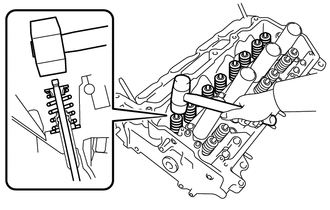
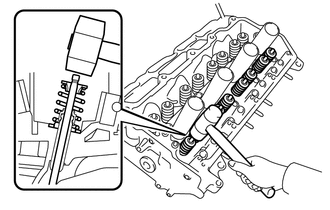
Using a plastic-faced hammer, lightly tap the valve stem tip to ensure a proper fit.
Note
-
Do not damage the valve stem tip.
-
Be careful not to damage the retainer.
-
-
-
-
INSTALL EXHAUST VALVE
Tech Tips
The shape of the inner compression spring determines whether the valve spring type described here is A or B.
-
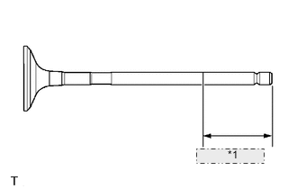
*1 40 mm or more Apply plenty of engine oil to the tip area of the exhaust valve shown in the illustration.
-
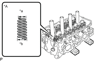
*A Valve Spring Type B *a Narrow *b Wide Install the valve, compression spring and spring retainer to the cylinder head.
Note
-
Install the same parts in the same combination to their original locations.
-
Valve Spring Type B:
Install the inner compression spring to the wide end of the cylinder head sub-assembly.
-
-
Valve Spring Type A:
-
Using SST and wooden blocks, compress the spring and install the retainer lock.
- SST
- 09202-70020 ( 09202-00010, 09202-01010, 09202-01020 )
-
Using a plastic-faced hammer, lightly tap the valve stem tip to ensure a proper fit.
Note
-
Do not damage the valve stem tip.
-
Be careful not to damage the retainer.
-
-
-
Valve Spring Type B:
-
Using SST and wooden blocks, compress the spring and install the retainer lock.
- SST
- 09202-70020 ( 09202-01010, 09202-01020 )
- 09202-00021
-
Using a plastic-faced hammer, lightly tap the valve stem tip to ensure a proper fit.
Note
-
Do not damage the valve stem tip.
-
Be careful not to damage the retainer.
-
-
-