CYLINDER HEAD DISASSEMBLY

CAUTION / NOTICE / HINT
Note
There are two cylinder head assembly shapes. Valve spring type A can only be used with cylinder head type A and valve spring type B can only be used with cylinder head type B. The combination cannot be changed.
Tech Tips
-
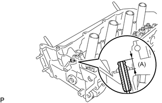
The standard protrusion amount (A) of the valve guide bush determines whether the cylinder head is type A or B.
Standard Protrusion Height (A) Type Specified Condition Cylinder Head Type A 14.3 to 14.7 mm (0.563 to 0.579 in.) Cylinder Head Type B 15.8 to 16.2 mm (0.622 to 0.638 in.) -
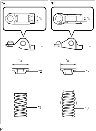
*A Valve Spring Type A *B Valve Spring Type B *1 No. 1 Valve Rocker Arm Sub-assembly *2 Valve Spring Retainer *3 Inner Compression Spring *a Valve Spring Retainer Outer Diameter *b No. 1 Valve Rocker Arm Roller Width The shape of the inner compression spring determines whether the valve spring type is A or B.
-
The No. 1 valve rocker arm, inner compression spring and valve spring retainer have two different shapes and are not interchangeable.
Valve Spring Type No. 1 Valve Rocker Arm Roller Width Valve Spring Retainer Outer Diameter Inner Compression Spring Shape A 10.7 mm (0.421 in.) 23.4 mm (0.921 in.) Straight B 8.0 mm (0.315 in.) 18.9 mm (0.744 in.) Taper
PROCEDURE
-
REMOVE INTAKE VALVE
Tech Tips
The shape of the inner compression spring determines whether the valve spring type is A or B.
-
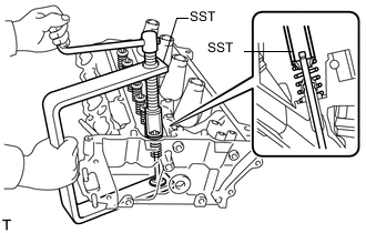
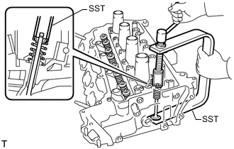
Valve Spring Type A:
-
Using SST and wooden blocks, compress the compression spring and remove the valve retainer lock.
- SST
- 09202-70020 ( 09202-00010, 09202-01010, 09202-01020 )
-
Remove the retainer, compression spring and valve.
Tech Tips
Arrange the removed parts in the correct order.
-
-
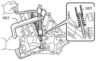
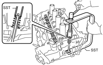
Valve Spring Type B:
-
Using SST and wooden blocks, compress the compression spring and remove the valve retainer lock.
- SST
- 09202-70020 ( 09202-01010, 09202-01020 )
- 09202-00021
-
Remove the retainer, compression spring and valve.
Tech Tips
Arrange the removed parts in the correct order.
-
-
-
REMOVE EXHAUST VALVE
Tech Tips
The shape of the inner compression spring determines whether the valve spring type is A or B.
-
Valve Spring Type A:
-
Using SST and wooden blocks, compress the compression spring and remove the valve retainer lock.
- SST
- 09202-70020 ( 09202-00010, 09202-01010, 09202-01020 )
-
Remove the retainer, compression spring and valve.
Tech Tips
Arrange the removed parts in the correct order.
-
-
Valve Spring Type B:
-
Using SST and wooden blocks, compress the compression spring and remove the valve retainer lock.
- SST
- 09202-70020 ( 09202-01010, 09202-01020 )
- 09202-00021
-
Remove the retainer, compression spring and valve.
Tech Tips
Arrange the removed parts in the correct order.
-
-
-
REMOVE VALVE STEM OIL SEAL
-
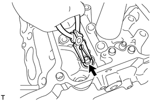
Using needle-nose pliers, remove the oil seals.
-
-
REMOVE VALVE SPRING SEAT
-
Using compressed air and a magnet hand, remove the valve spring seat by blowing air onto it.
-
-
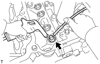
REMOVE NO. 1 STRAIGHT SCREW PLUG
Note
If water leaks from the No. 1 screw plug or the plug is corroded, replace it.
-
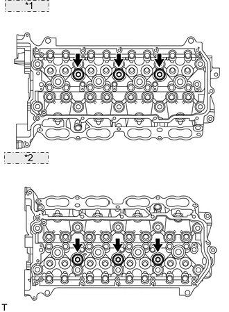
*1 for Bank 2: *2 for Bank 1: Using a 10 mm hexagon wrench, remove the 6 screw plugs and 6 gaskets.
-
-
REMOVE NO. 2 STRAIGHT SCREW PLUG
-
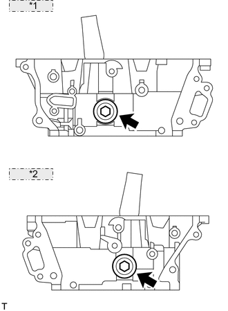
*1 for Bank 2: *2 for Bank 1: Using a 14 mm hexagon wrench, remove the 2 screw plugs and 2 gaskets.
Note
If water leaks from the No. 2 screw plug or the plug is corroded, replace it.
-
-
REMOVE STUD BOLT
Note
If a stud bolt is deformed or its threads are damaged, replace it.