ENGINE UNIT REASSEMBLY

PROCEDURE
-
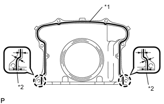
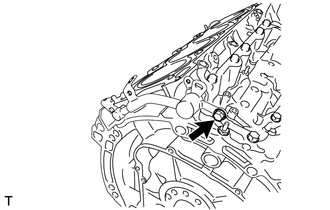
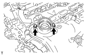
INSTALL OIL PAN STUD BOLT
Note
If a stud bolt is deformed or the threads are damaged, replace it.
-
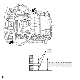
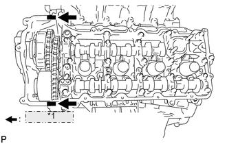
*1 9 mm (0.354 in.) *2 19 mm (0.748 in.) for 2WD:
Using an E6 "TORX" socket wrench, install the 2 stud bolts as shown in the illustration.
- Torque:
- 5.0 N*m { 51 kgf*cm, 44 in.*lbf }
-
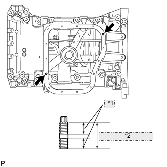
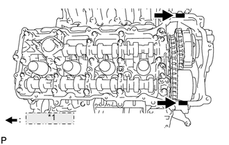
*1 9 mm (0.354 in.) *2 19 mm (0.748 in.) for AWD:
Using an E6 "TORX" socket wrench, install the 2 stud bolts as shown in the illustration.
- Torque:
- 5.0 N*m { 51 kgf*cm, 44 in.*lbf }
-
-
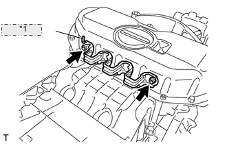
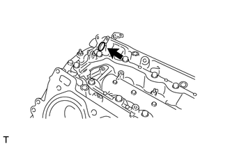
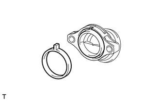
INSTALL NO. 1 VENTILATION CONNECTOR
-
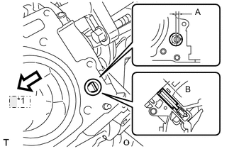
*1 Front Install the No. 1 ventilation connector as shown in the illustration.
Acceptable angle (A) -5 to 5° Tap-in depth (B) 0.2 to 3.2 mm (0.008 to 0.126 in.) Note
After the installation of the ventilation connector, do not rotate it.
Tech Tips
Connect the No. 1 ventilation connector so that its flat surface faces the rear part of the engine.
-
-
INSTALL OIL DRAIN PIPE SUB-ASSEMBLY
-
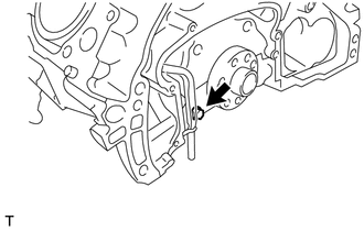
Apply a light coat of engine oil to a new O-ring.
-
Install the new O-ring to the drain pipe.
-
Install the oil drain pipe with the bolt.
- Torque:
- 10 N*m { 102 kgf*cm, 7 ft.*lbf }
-
-
INSTALL ENGINE REAR OIL SEAL RETAINER
-
*1 2.0 to 3.0 mm *2 3.5 mm Apply seal packing in a continuous line as shown in the illustration.
Seal packing Toyota Genuine Seal Packing Black, Three Bond 1207B or equivalent Seal diameter 2.0 to 3.0 mm (0.079 to 0.118 in.) Application position from inside edge of retainer 3.5 mm (0.138 in.) Note
-
Remove any oil from the contact surface.
-
Install the oil pan within 3 minutes and tighten the bolts and nuts within 15 minutes after applying seal packing.
-
Do not start the engine for at least 2 hours after installing.
-
When installing the oil seal retainer, make sure the lip of the oil seal is not damaged.
-
When installing the oil seal retainer, make sure the lip of the oil seal is not folded incorrectly.
-
-
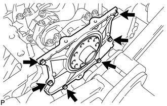
Install the oil seal retainer with the 6 bolts.
- Torque:
- 10 N*m { 102 kgf*cm, 7 ft.*lbf }
-
-
INSTALL OIL STRAINER SUB-ASSEMBLY
-
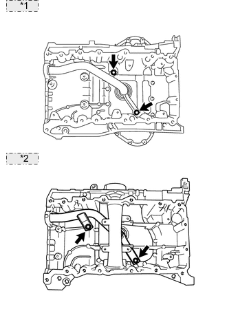
*1 for 2WD: *2 for AWD: Apply a light coat of engine oil to a new O-ring.
-
Install the new O-ring to the oil strainer.
-
Install the oil strainer with the 2 bolts.
- Torque:
- 21 N*m { 214 kgf*cm, 15 ft.*lbf }
Note
Make sure the O-ring is not twisted or damaged.
-
-
INSTALL NO. 2 OIL PAN BAFFLE PLATE (for AWD)
-
Install the baffle plate with the 4 bolts.
- Torque:
- 10 N*m { 102 kgf*cm, 7 ft.*lbf }
-
-
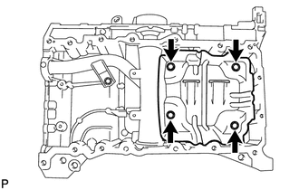
INSTALL NO. 1 OIL PAN BAFFLE PLATE
-
for 2WD:
Install the baffle plate with the 8 bolts.
- Torque:
- 10 N*m { 102 kgf*cm, 7 ft.*lbf }
-
for AWD:
Install the baffle plate with the 4 bolts.
- Torque:
- 10 N*m { 102 kgf*cm, 7 ft.*lbf }
-
-
INSTALL OIL PAN SUB-ASSEMBLY
-
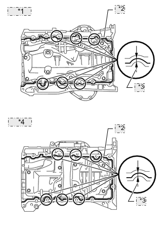
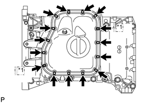
*1 for 2WD: *2 3.0 to 4.0 mm *3 6.0 mm *4 for AWD: Apply seal packing in a continuous line as shown in the illustration.
Seal packing Toyota Genuine Seal Packing Black, Three Bond 1207B or equivalent Standard seal diameter 3.0 to 4.0 mm (0.118 to 0.156 in.) Application position from inside edge of oil pan 6.0 mm (0.236 in.) Note
-
Remove any oil from the contact surface.
-
Install the oil pan within 3 minutes and tighten the bolts and nuts within 15 minutes after applying seal packing.
-
-
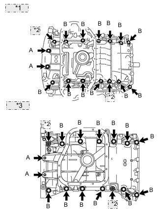
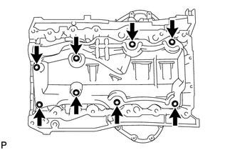
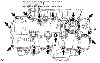
*1 for 2WD: *2 Nut *3 for AWD: Install the oil pan with the 14 bolts and 2 nuts.
- Torque:
- for bolt A
- 10 N*m { 102 kgf*cm, 7 ft.*lbf }
- for bolt B and nut
- 35 N*m { 357 kgf*cm, 26 ft.*lbf }
Note
Do not start the engine for at least 2 hours after installing.
-
-
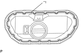
INSTALL OIL PAN PROTECTOR (for 2WD)
*1 Protrusion
-
Install the protector with the 2 nuts.
- Torque:
- 5.0 N*m { 51 kgf*cm, 44 in.*lbf }
Tech Tips
Install the oil pan protector with its protrusion facing the bottom of the engine.
-
-
INSTALL NO. 2 OIL PAN SUB-ASSEMBLY
-
*1 3.0 to 4.0 mm for 2WD:
-
Apply seal packing in a continuous line as shown in the illustration.
Seal packing Toyota Genuine Seal Packing Black, Three Bond 1207B or equivalent Standard seal diameter 3.0 to 4.0 mm (0.118 to 0.156 in.) Note
-
Remove any oil from the contact surface.
-
Install the oil pan within 3 minutes and tighten the bolts and nuts within 10 minutes after applying seal packing.
-
Do not start the engine for at least 2 hours after installing.
-
-
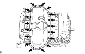
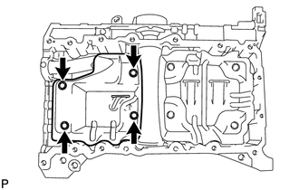
*1 Nut Install the oil pan with the 15 bolts and 2 nuts.
- Torque:
- 10 N*m { 102 kgf*cm, 7 ft.*lbf }
-
-
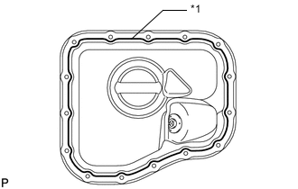
*1 3.0 to 4.0 mm for AWD:
-
Apply seal packing in a continuous line as shown in the illustration.
Seal packing Toyota Genuine Seal Packing Black, Three Bond 1207B or equivalent Standard seal diameter 3.0 to 4.0 mm (0.118 to 0.157 in.) Note
-
Remove any oil from the contact surface.
-
Install the oil pan within 3 minutes and tighten the bolts and nuts within 10 minutes after applying seal packing.
-
-
*1 Nut Install the oil pan with the 13 bolts and 2 nuts.
- Torque:
- 10 N*m { 102 kgf*cm, 7 ft.*lbf }
Note
Do not start the engine for at least 2 hours after installing.
-
-
-
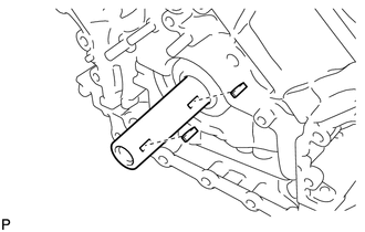
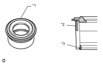
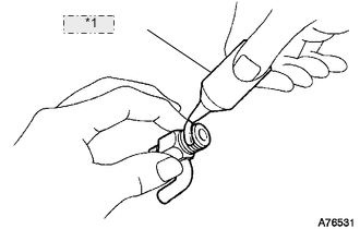
INSTALL VENTILATION PIPE GASKET
-
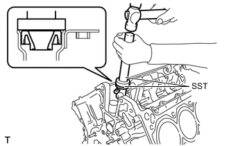
Using SST, evenly tap in a new ventilation pipe gasket until its surface is flush with the lip of the ventilation pipe.
- SST
- 09950-60010 ( 09951-00360 )
- 09950-70010 ( 09951-07100 )
Tech Tips
-
Do not tap the gasket at an angle.
-
Do not tap the gasket excessively.
-
-
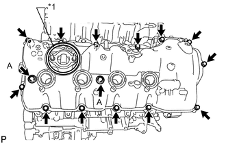
INSTALL NO. 1 HEAT EXCHANGER COVER
-
*1 3.0 to 4.0 mm Apply seal packing in a continuous line as shown in the illustration.
Seal packing Toyota Genuine Seal Packing 1282B, Three Bond 1282B or equivalent Standard seal diameter 3.0 to 4.0 mm (0.118 to 0.157 in.) Note
-
Remove any oil from the contact surface.
-
Install the heat exchanger cover within 3 minutes and tighten the bolts and nuts within 15 minutes after applying seal packing.
-
-
*1 Nut Install the heat exchanger cover with the 11 bolts and 2 nuts.
- Torque:
- 21 N*m { 214 kgf*cm, 15 ft.*lbf }
Note
Do not start the engine for at least 2 hours after installing.
-
Install the bolt.
- Torque:
- 10 N*m { 102 kgf*cm, 7 ft.*lbf }
-
-
INSTALL OIL RETURN PIPE GASKET
-
Install a new oil return pipe gasket.
-
-
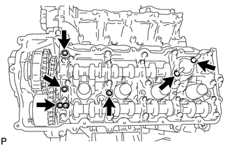
INSTALL CYLINDER BLOCK WATER JACKET SPACER
-
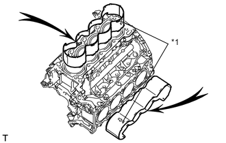
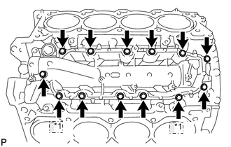
*1 "UP"Mark Install the 2 water jacket spacers as shown in the illustration.
Tech Tips
-
Face the cutouts (indicated by arrows in illustration) away from the engine.
-
Face the "up mark" as shown in the illustration.
-
-
-
INSTALL CYLINDER HEAD SUB-ASSEMBLY (for Bank 1)
-
INSTALL CYLINDER HEAD SUB-ASSEMBLY (for Bank 2)
-
INSTALL VALVE STEM CAP
-
Apply a light coat of engine oil to the valve stem caps.
-
Install the 32 valve stem caps to the cylinder head.
-
-
INSTALL VALVE LASH ADJUSTER ASSEMBLY
-
Be sure to inspect the valve lash adjuster before installing it Click here.
-
Install the 32 valve lash adjusters to the cylinder head.
Note
Install the lash adjuster at the same place it was removed from.
-
-
INSTALL NO. 1 VALVE ROCKER ARM SUB-ASSEMBLY
-
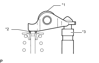
Text in Illustration *1 No. 1 Valve Rocker Arm Sub-assembly *2 Valve Stem Cap *3 Valve Lash Adjuster Assembly Apply engine oil to the lash adjuster tips and valve stem cap ends.
-
Make sure that the 32 valve rocker arms are installed as shown in the illustration.
-
-
INSTALL CAMSHAFT BEARING CAP (for Bank 2)
-
INSTALL CAMSHAFT HOUSING SUB-ASSEMBLY (for Bank 2)
-
INSTALL CAMSHAFT BEARING CAP (for Bank 1)
-
INSTALL CAMSHAFT HOUSING SUB-ASSEMBLY (for Bank 1)
-
INSTALL CRANKSHAFT TIMING GEAR KEY
-
Install the 2 timing gear keys.
-
-
SET NO. 1 CYLINDER TO TDC / COMPRESSION
-
INSTALL NO. 2 CHAIN TENSIONER ASSEMBLY
-
INSTALL CHAIN SUB-ASSEMBLY (for Bank 2)
-
INSTALL NO. 1 CHAIN VIBRATION DAMPER (for Bank 2)
-
INSTALL CHAIN TENSIONER SLIPPER (for Bank 2)
-
INSTALL NO. 1 CHAIN TENSIONER ASSEMBLY (for Bank 2)
-
INSTALL NO. 3 CHAIN TENSIONER ASSEMBLY
-
INSTALL CHAIN SUB-ASSEMBLY (for Bank 1)
-
INSTALL CHAIN TENSIONER SLIPPER (for Bank 1)
-
INSTALL NO. 1 CHAIN TENSIONER ASSEMBLY (for Bank 1)
-
INSTALL NO. 1 CHAIN VIBRATION DAMPER (for Bank 1)
-
TIGHTEN CAMSHAFT TIMING GEAR ASSEMBLY
-
CHECK NO. 1 CYLINDER TO TDC / COMPRESSION
-
INSTALL WATER INLET PIPE
-
INSTALL WATER PUMP ASSEMBLY
-
INSTALL TIMING CHAIN COVER SUB-ASSEMBLY
-
INSTALL OIL CONTROL VALVE FILTER
-
for Bank 1:
-
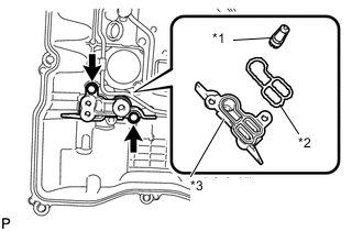
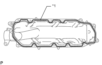
*1 Filter *2 Gasket *3 Cylinder Head Cover Spacer Install the valve filter in the cylinder head.
-
Install a new gasket and the cylinder head cover spacer with the 2 bolts.
- Torque:
- 10 N*m { 102 kgf*cm, 7 ft.*lbf }
-
-
for Bank 2:
-
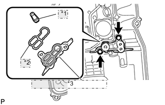
*1 Filter *2 Gasket *3 Cylinder Head Cover Spacer Install the valve filter in the cylinder head.
-
Install a new gasket and the cylinder head cover spacer with the 2 bolts.
- Torque:
- 10 N*m { 102 kgf*cm, 7 ft.*lbf }
-
-
-
INSTALL CYLINDER HEAD COVER SUB-ASSEMBLY LH
-
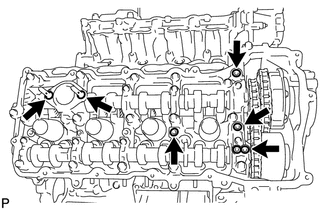
Install 4 new gaskets and 2 new O-rings to the camshaft bearing caps (No. 2, No. 3, No. 7).
-
Install a new gasket to the cylinder head cover.
Note
Remove any oil from the contact surface.
-
*1 Seal Packing Apply seal packing as shown the illustration.
Seal packing Toyota Genuine Seal Packing Black, Three Bond 1207B or equivalent Note
-
Remove any oil from the contact surface.
-
Install the cylinder head cover within 3 minutes and tighten the bolts within 15 minutes after applying seal packing.
-
Do not start the engine for at least 2 hours after the installation.
-
-
*1 Fuel Pump Spacer Gasket Install the cylinder head cover with 2 new seal washers and the 15 bolts.
- Torque:
- for bolt A
- 21 N*m { 214 kgf*cm, 15 ft.*lbf }
- except bolt A
- 12 N*m { 122 kgf*cm, 9 ft.*lbf }
-
Install the fuel pump spacer gasket.
-
-
INSTALL CYLINDER HEAD COVER SUB-ASSEMBLY RH
-
Install 4 new gaskets and 2 new O-rings to the camshaft bearing caps. (No. 1, No. 3, No. 6).
-
Install a new gasket to the cylinder head cover.
Note
Remove any oil from the contact surface.
-
*1 Seal Packing Apply seal packing as shown the illustration.
Seal packing Toyota Genuine Seal Packing Black, Three Bond 1207B or equivalent Note
-
Remove any oil from the contact surface.
-
Install the cylinder head cover within 3 minutes and tighten the bolts within 15 minutes after applying seal packing.
-
Do not start the engine for at least 2 hours after the installation.
-
-
*1 Fuel Pump Spacer Gasket Install the cylinder head cover with 2 new seal washers and the 15 bolts.
- Torque:
- for bolt A
- 21 N*m { 214 kgf*cm, 15 ft.*lbf }
- except bolt A
- 12 N*m { 122 kgf*cm, 9 ft.*lbf }
-
Install the fuel pump spacer gasket.
-
-
INSTALL SPARK PLUG TUBE GASKET
-
*1 Upper Surface *2 Outer Lip *3 Inner Lip Perform a visual inspection on the spark plug tube gasket.
Standard Area Specified Condition Upper surface No scratches or deformation Outer lip No scratches or deformation Inner lip No scratches -
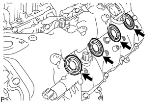
Install the 8 plug tube gaskets to the cylinder head cover.
-
-
INSTALL TIMING CHAIN CASE OIL SEAL
-
INSTALL CRANKSHAFT PULLEY
-
INSTALL FRONT WATER BY-PASS JOINT
-
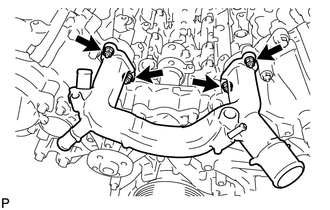
Install the 2 new gaskets and water by-pass joint with the 4 nuts.
- Torque:
- 21 N*m { 214 kgf*cm, 15 ft.*lbf }
-
-
INSTALL OIL FILTER BRACKET (for 2WD)
-
INSTALL OIL FILTER BRACKET (for AWD)
-
INSTALL OIL FILTER ELEMENT (for 2WD)
-
INSTALL OIL FILTER ELEMENT (for AWD)
-
INSTALL CYLINDER BLOCK WATER DRAIN COCK SUB-ASSEMBLY
-
*1 Adhesive Apply adhesive to 2 or 3 threads of the drain cock.
Adhesive Toyota Genuine Adhesive 1344, Three Bond 1344 or equivalent -
Install the water drain cocks as shown in the illustration.
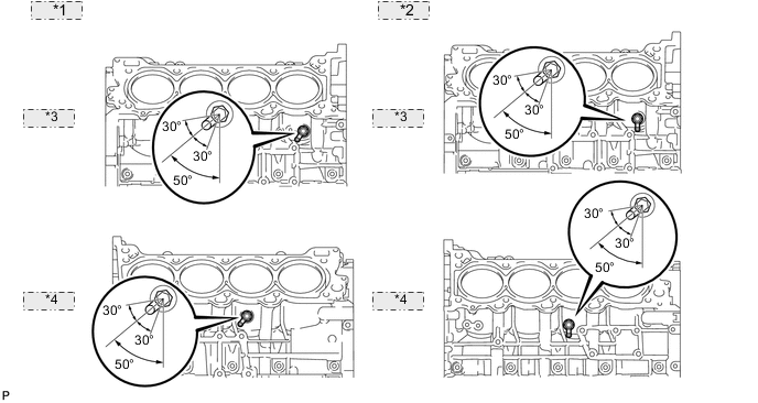
*1 for 2WD: *2 for AWD: *3 RH Side: *4 LH Side: - Torque:
- 30 N*m { 306 kgf*cm, 22 ft.*lbf }
Note
-
Do not rotate the drain cocks more than 1 revolution (360°) after tightening the drain cocks with the specified torque.
-
Do not loosen the drain cocks to adjust them. If an adjustment is necessary, remove the drain cocks and reinstall them.
-
Install the water drain cock plugs to the water drain cocks.
- Torque:
- 13 N*m { 133 kgf*cm, 10 ft.*lbf }
-
-
INSTALL CAMSHAFT TIMING CONTROL WITH EDU MOTOR ASSEMBLY LH
-
INSTALL CAMSHAFT TIMING CONTROL WITH EDU MOTOR ASSEMBLY RH
-
INSTALL CAMSHAFT TIMING OIL CONTROL VALVE ASSEMBLY
-
for Bank 1:
-
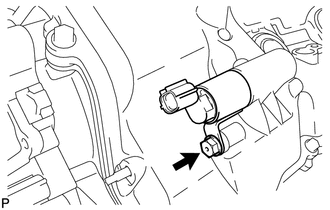
Apply a light coat of engine oil to a new O-ring.
-
Install the O-ring to the oil control valve.
-
Install the oil control valve with the bolt.
- Torque:
- 10 N*m { 102 kgf*cm, 7 ft.*lbf }
-
-
for Bank 2:
-
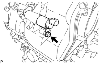
Apply a light coat of engine oil to a new O-ring.
-
Install the O-ring to the oil control valve.
-
Install the oil control valve with the bolt.
- Torque:
- 10 N*m { 102 kgf*cm, 7 ft.*lbf }
-
-
-
INSTALL CRANKSHAFT POSITION SENSOR
-
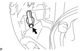
Install the crankshaft position sensor with the bolt.
- Torque:
- 10 N*m { 102 kgf*cm, 7 ft.*lbf }
-
-
INSTALL CAMSHAFT POSITION SENSOR
-
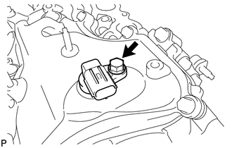
Install the camshaft position sensor with the bolt.
- Torque:
- 10 N*m { 102 kgf*cm, 7 ft.*lbf }
-
-
INSTALL VVT SENSOR
-
for Bank 1:
-
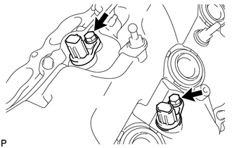
Install the 2 VVT sensors with the 2 bolts.
- Torque:
- 10 N*m { 102 kgf*cm, 7 ft.*lbf }
-
-
for Bank 2:
-
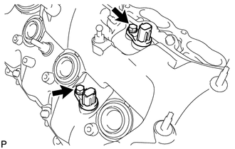
Install the 2 VVT sensors with the 2 bolts.
- Torque:
- 10 N*m { 102 kgf*cm, 7 ft.*lbf }
-
-
-
INSTALL SPARK PLUG
-
INSTALL OIL FILLER CAP HOUSING
-
Align the protrusion of a new gasket with the cutout of the oil filler cap housing, and install the gasket to the housing.
-
Install the cap housing with the 2 bolts.
- Torque:
- 10 N*m { 102 kgf*cm, 7 ft.*lbf }
-
-
INSTALL OIL FILLER CAP SUB-ASSEMBLY