ENGINE UNIT DISASSEMBLY

PROCEDURE
-
REMOVE OIL FILLER CAP SUB-ASSEMBLY
-
REMOVE OIL FILLER CAP HOUSING
-
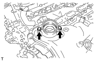
Remove the 2 bolts, filler cap housing and gasket.
-
-
REMOVE SPARK PLUG
-
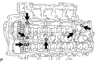
REMOVE VVT SENSOR
-
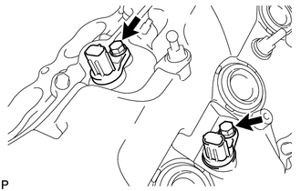
for Bank 1:
Remove the 2 bolts and 2 VVT sensors.
-
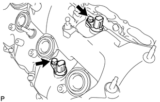
for Bank 2:
Remove the 2 bolts and 2 VVT sensors.
-
-
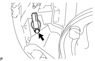
REMOVE CAMSHAFT POSITION SENSOR
-
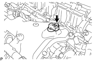
Remove the bolt and camshaft position sensor.
-
-
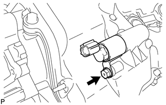
REMOVE CRANKSHAFT POSITION SENSOR
-
Remove the bolt and crankshaft position sensor.
-
-
REMOVE CAMSHAFT TIMING OIL CONTROL VALVE ASSEMBLY
-
for Bank 1:
Remove the bolt and oil control valve.
-
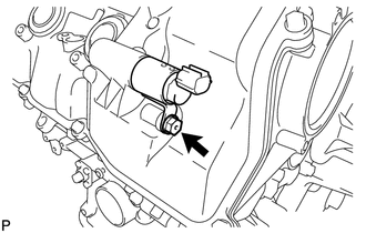
for Bank 2:
Remove the bolt and oil control valve.
-
-
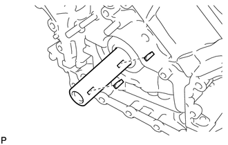
REMOVE CYLINDER BLOCK WATER DRAIN COCK SUB-ASSEMBLY
-
Remove the 2 water drain cock plugs from the water drain cocks.
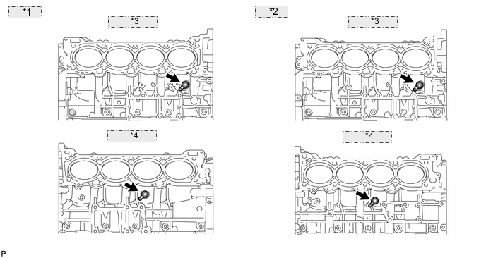
*1 for 2WD: *2 for AWD: *3 Bank 2 Side: *4 Bank 1 Side: -
Remove the 2 water drain cocks from the cylinder block.
-
-
REMOVE CAMSHAFT TIMING CONTROL WITH EDU MOTOR ASSEMBLY LH
-
REMOVE CAMSHAFT TIMING CONTROL WITH EDU MOTOR ASSEMBLY RH
-
REMOVE OIL FILTER ELEMENT (for 2WD)
-
REMOVE OIL FILTER ELEMENT (for AWD)
-
REMOVE OIL FILTER BRACKET (for 2WD)
-
REMOVE OIL FILTER BRACKET (for AWD)
-
REMOVE FRONT WATER BY-PASS JOINT
-
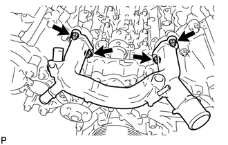
Remove the 4 nuts, water by-pass joint and 2 gaskets.
-
-
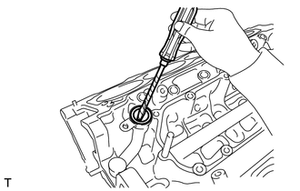
REMOVE SPARK PLUG TUBE GASKET
-
*1 Keyway Part Using a screwdriver, pry out the 8 plug tube gaskets.
Tech Tips
Tape the screwdriver tip before use.
-
-
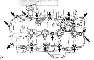
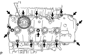
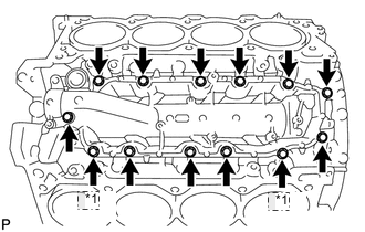
REMOVE CYLINDER HEAD COVER SUB-ASSEMBLY LH
-
*1 Fuel Pump Spacer Gasket Remove the fuel pump spacer gasket.
-
Remove the 15 bolts, 2 seal washers, cylinder head cover and gasket.
Tech Tips
Make sure the removed parts are returned to the same places they were removed from.
-
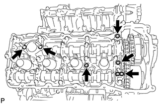
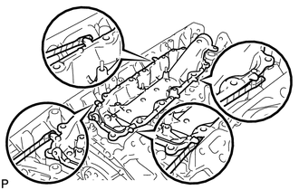
Remove the 4 gaskets and 2 O-rings from the camshaft bearing caps (No. 2, No. 3, No. 7).
-
-
REMOVE CYLINDER HEAD COVER SUB-ASSEMBLY RH
-
*1 Fuel Pump Spacer Gasket Remove the fuel pump spacer gasket.
-
Remove the 15 bolts, 2 seal washers, cylinder head cover and gasket.
Tech Tips
Make sure the removed parts are returned to the same places they were removed from.
-
Remove the 4 gaskets and 2 O-rings from the camshaft bearing caps (No. 1, No. 3, No. 6).
-
-
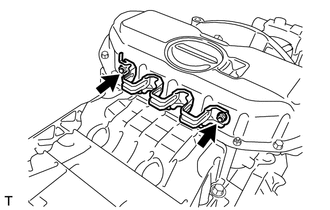
REMOVE OIL CONTROL VALVE FILTER
-
for Bank 1:
-
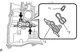
*1 Filter *2 Gasket *3 Cylinder Head Cover Spacer Remove the 2 bolts, cylinder head cover spacer, gasket and valve filter.
-
-
for Bank 2:
-
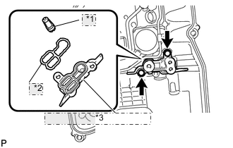
*1 Filter *2 Gasket *3 Cylinder Head Cover Spacer Remove the 2 bolts, cylinder head cover spacer, gasket and valve filter.
-
-
-
REMOVE V-RIBBED BELT TENSIONER ASSEMBLY
-
REMOVE CRANKSHAFT PULLEY
-
REMOVE WATER PUMP ASSEMBLY
-
REMOVE TIMING CHAIN COVER SUB-ASSEMBLY
-
REMOVE TIMING CHAIN CASE OIL SEAL
-
REMOVE WATER INLET PIPE
-
SET NO. 1 CYLINDER TO TDC / COMPRESSION
-
REMOVE NO. 1 CHAIN TENSIONER ASSEMBLY (for Bank 1)
-
REMOVE CHAIN TENSIONER SLIPPER (for Bank 1)
-
REMOVE NO. 1 CHAIN VIBRATION DAMPER (for Bank 1)
-
REMOVE CHAIN SUB-ASSEMBLY (for Bank 1)
-
REMOVE NO. 3 CHAIN TENSIONER ASSEMBLY
-
REMOVE NO. 1 CHAIN TENSIONER ASSEMBLY (for Bank 2)
-
REMOVE CHAIN TENSIONER SLIPPER (for Bank 2)
-
REMOVE NO. 1 CHAIN VIBRATION DAMPER (for Bank 2)
-
REMOVE CHAIN SUB-ASSEMBLY (for Bank 2)
-
REMOVE NO. 2 CHAIN TENSIONER ASSEMBLY
-
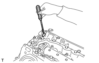
REMOVE CRANKSHAFT TIMING GEAR KEY
-
Using a screwdriver, remove the 2 timing gear keys from the crankshaft.
-
-
REMOVE CAMSHAFT BEARING CAP (for Bank 2)
-
REMOVE CAMSHAFT HOUSING SUB-ASSEMBLY (for Bank 2)
-
REMOVE CAMSHAFT BEARING CAP (for Bank 1)
-
REMOVE CAMSHAFT HOUSING SUB-ASSEMBLY (for Bank 1)
-
REMOVE NO. 1 VALVE ROCKER ARM SUB-ASSEMBLY
-
Remove the 32 valve rocker arms from the cylinder head.
Tech Tips
Arrange the removed parts in the correct order.
-
-
REMOVE VALVE LASH ADJUSTER ASSEMBLY
-
Remove the 32 valve lash adjusters from the cylinder head.
Tech Tips
Arrange the removed parts in the correct order.
-
-
REMOVE VALVE STEM CAP
-
Remove the 32 valve stem caps from the cylinder head.
Tech Tips
Arrange the removed parts in the correct order.
-
-
REMOVE CYLINDER HEAD SUB-ASSEMBLY (for Bank 1)
-
REMOVE CYLINDER HEAD SUB-ASSEMBLY (for Bank 2)
-
REMOVE CYLINDER BLOCK WATER JACKET SPACER
-
Remove the 2 water jacket spacers from the cylinder head.
Note
Be sure to remove the water jacket spacers. If not, they may fall and become damaged when the cylinder block is inverted.
-
-
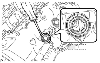
REMOVE OIL RETURN PIPE GASKET
-
Using a screwdriver, pry out the oil return pipe gasket.
Tech Tips
Tape the screwdriver tip before use.
-
-
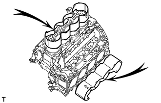
REMOVE NO. 1 HEAT EXCHANGER COVER
-
Remove the bolt.
-
*1 Nut Remove the 11 bolts and 2 nuts.
-
Remove the heat exchanger by prying between the heat exchanger and cylinder block with a screwdriver.
Tech Tips
Tape the screwdriver tip before use.
-
-
REMOVE VENTILATION PIPE GASKET
-
Using a screwdriver, pry out the ventilation pipe gasket.
Tech Tips
Tape the screwdriver tip before use.
-
-
REMOVE OIL PAN PROTECTOR (for 2WD)
-
Remove the 2 nuts and oil pan protector.
-
-
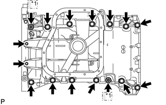
REMOVE NO. 2 OIL PAN SUB-ASSEMBLY
-
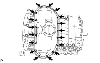
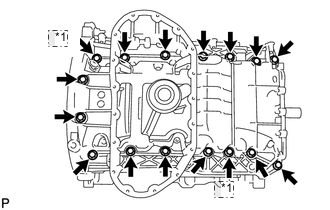
*1 Nut for 2WD:
Remove the 15 bolts and 2 nuts.
-
*1 Nut for AWD:
Remove the 13 bolts and 2 nuts.
-
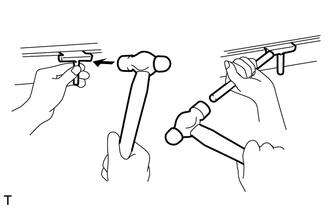
Insert the blade of oil pan seal cutter between the oil pans. Cut through the applied sealer and remove the No. 2 oil pan.
Note
Be careful not to damage the contact surfaces of the oil pans.
-
-
REMOVE OIL PAN SUB-ASSEMBLY
-
for 2WD:
-
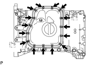
*1 Nut Remove the 14 bolts and 2 nuts.
Tech Tips
Be sure to clean the bolts and stud bolts, and check the threads for cracks or other damage.
-
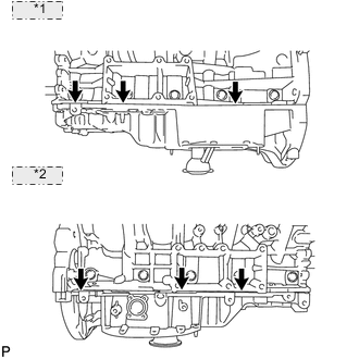
*1 LH Side: *2 RH Side: Remove the oil pan by prying between the oil pan and cylinder block with a screwdriver.
Note
Be careful not to damage the contact surfaces of the cylinder block and oil pan.
Tech Tips
Tape the screwdriver tip before use.
-
-
*1 Nut for AWD:
-
Remove the 14 bolts and 2 nuts.
Tech Tips
Be sure to clean the bolts and stud bolts, and check the threads for cracks or other damage.
-
*1 LH Side: *2 RH Side: Remove the oil pan by prying between the oil pan and cylinder block with a screwdriver.
Note
Be careful not to damage the contact surfaces of the cylinder block and oil pan.
Tech Tips
Tape the screwdriver tip before use.
-
-
-
REMOVE NO. 1 OIL PAN BAFFLE PLATE
-
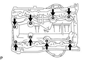
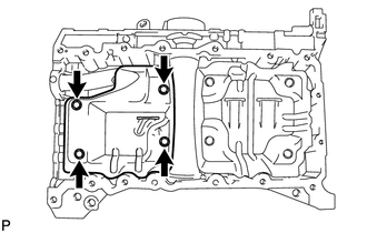
for 2WD:
Remove the 8 bolts and baffle plate.
-
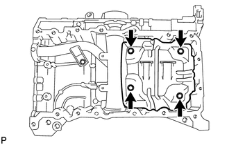
for AWD:
Remove the 4 bolts and baffle plate.
-
-
REMOVE NO. 2 OIL PAN BAFFLE PLATE (for AWD)
-
Remove the 4 bolts and baffle plate.
-
-
REMOVE OIL STRAINER SUB-ASSEMBLY
-
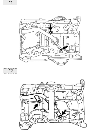
*1 for 2WD: *2 for AWD: Remove the 2 bolts, oil strainer and O-ring.
-
-
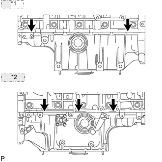
REMOVE ENGINE REAR OIL SEAL RETAINER
-
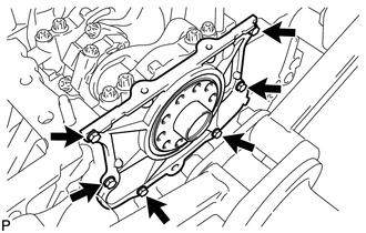
Remove the 6 bolts.
-
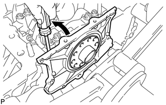
Using a screwdriver, pry out the oil seal retainer.
Tech Tips
Tape the screwdriver tip before use.
-
-
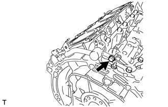
REMOVE OIL DRAIN PIPE SUB-ASSEMBLY
-
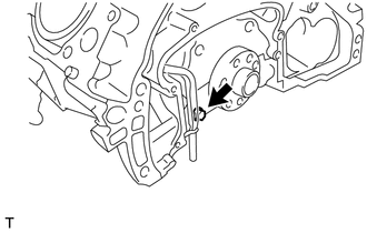
Remove the bolt and oil drain pipe.
-
Remove the O-ring.
-
-
REMOVE NO. 1 VENTILATION CONNECTOR
-
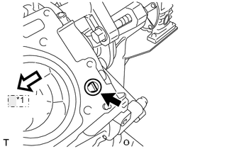
*1 Front Remove the ventilation connector.
Tech Tips
When removing the ventilation connector, the ventilation tube may come off the ventilation connector. If this occurs, do not forget to remove it from the cylinder block.
If the ventilation tube comes off, check for deformation and damage. If normal, attach the ventilation tube to the ventilation connector. If deformed or damaged, replace the ventilation connector assembly.
-
-
REMOVE OIL PAN STUD BOLT
Tech Tips
If the stud bolt is deformed or its threads are damaged, replace it.