AUTOMATIC TRANSMISSION SYSTEM, Diagnostic DTC:P2759
| DTC Code | DTC Name |
|---|---|
| P2759 | Torque Converter Clutch Pressure Control Solenoid Control Circuit Electrical (Shift Solenoid Valve SLU) |
DESCRIPTION
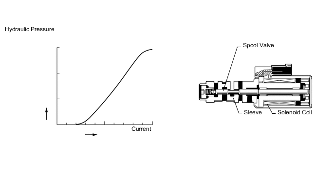
The TCM controls the lock-up solenoid using a predetermined the current, and performs lock-up and flex lock-up control.
| DTC Code | DTC Detection Condition
|
Trouble Area |
|---|---|---|
| P2759 |
|
|
MONITOR DESCRIPTION
When an open or short in the shift solenoid valve SLU circuit is detected, the TCM determines that there is a malfunction. The TCM will illuminate the MIL and store this DTC.
WIRING DIAGRAM
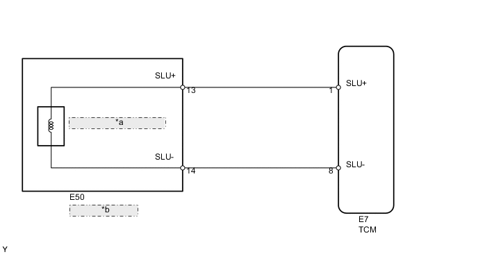
| *a | Shift Solenoid Valve SLU |
| *b | Transmission Wire |
PROCEDURE
-
CHECK HARNESS AND TRANSMISSION WIRE (TRANSMISSION WIRE - TCM, TRANSMISSION WIRE (SHIFT SOLENOID VALVE SLU))
-
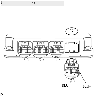
*1 Rear view of wire harness connector: (to TCM) Disconnect the E7 TCM connector.
-
Measure the resistance according to the value(s) in the table below.
Standard Resistance Tester Connection Condition Specified Condition E7-1 (SLU+) - E7-8 (SLU-) Always 5.0 to 5.6 Ω E7-1 (SLU+) or E7-8 (SLU-) - Body ground Always 10 kΩ or higher
NG 
CHECK HARNESS AND CONNECTOR (TRANSMISSION WIRE - TCM) Click here
OK 
-
-
REPLACE TCM
-
Replace the TCM Click here.
NEXT 
PERFORM A/T CODE REGISTRATION Click here
-
-
CHECK HARNESS AND CONNECTOR (TRANSMISSION WIRE - TCM)
-
Disconnect the E50 transmission wire connector.
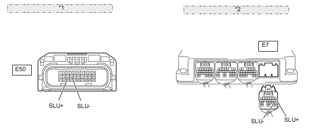
*1 Front view of wire harness connector: (to Transmission Wire) *2 Rear view of wire harness connector: (to TCM) -
Disconnect the E7 TCM connector.
-
Measure the resistance according to the value(s) in the table below.
Standard Resistance Tester Connection Condition Specified Condition E50-13 (SLU+) - E7-1 (SLU+) Always Below 1 Ω E50-14 (SLU-) - E7-8 (SLU-) Always Below 1 Ω E50-13 (SLU+) or E7-1 (SLU+) - Body ground Always 10 kΩ or higher E50-14 (SLU-) or E7-8 (SLU-) - Body ground Always 10 kΩ or higher
NG
REPAIR OR REPLACE HARNESS OR CONNECTOR
OK
-
-
INSPECT SHIFT SOLENOID VALVE SLU
-
Remove shift solenoid valve SLU Click here.
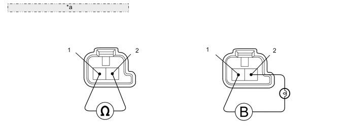
*a Component without harness connected: (Shift Solenoid Valve SLU) -
Measure the resistance according to the value(s) in the table below.
Standard resistance Tester Connection Condition Specified Condition Terminal 1 of shift solenoid valve SLU - Terminal 2 20°C (68°F) 5.0 to 5.6 Ω -
Connect the battery's positive (+) lead with a 21 W bulb to terminal 2 and the negative (-) lead to terminal 1 of the solenoid valve connector. Then check that the valve moves and makes an operating noise.
OK Valve moves and makes operating noise.
OK
REPAIR OR REPLACE TRANSMISSION WIRE Click here
NG
REPLACE SHIFT SOLENOID VALVE SLU Click here
-