-
Click here
BEARING POSITION
Mark Front Race Diameter Inside / Outside mm (in.) Thrust Bearing Diameter Inside / Outside mm (in.) Rear Race Diameter Inside / Outside mm (in.) A 28.45 (1.120) / 47.3 (1.862) 29.2 (1.15) / 50.2 (1.976) - B 28.8 (1.134) / 46.4 (1.827) 28.9 (1.138) / 50.2 (1.976) - C 24.7 (0.972) / 41.8 (1.646) 24.2 (0.953) / 47.8 (1.882) - D 37.2 (1.465) / 58.8 (2.315) 33.8 (1.331) / 50.0 (1.969) - E 36.8 (1.449) / 50.9 (2.004) 33.7 (1.327) / 47.6 (1.874) - F 26.0 (1.024) / 48.9 (1.926) 26.0 (1.024) / 46.7 (1.839) 26.8 (1.055) / 47.0 (1.850) G - 35.2 (1.386) / 53.6 (2.110) 34.3 (1.350) / 47.8 (1.882) H 33.7 (1.327) / 47.6 (1.874) 35.5 (1.398) / 47.7 (1.878) - I 28.5 (1.122) / 44.2 (1.740) 27.7 (1.091) / 44.2 (1.740) - J - 39.38 (1.550) / 58.1 (2.287) - - Click here
FIX AUTOMATIC TRANSMISSION CASE SUB-ASSEMBLY
-
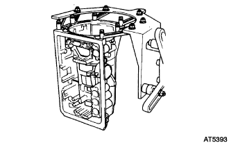
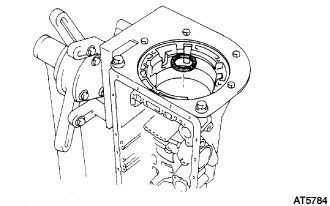
Install the transmission case in the overhaul attachment.
-
- Click here
INSTALL 1ST AND REVERSE BRAKE PISTON NO.1
-
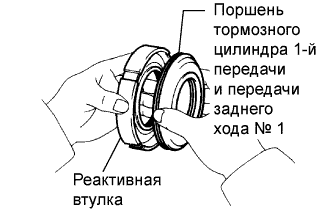
Coat 3 new O-rings with ATF.
-
Install the 2 O-rings on the 1st and reverse brake piston No.1.
-
Install the O-ring on the reaction sleeve.
-
Install the 1st and reverse brake piston No.1 to the reaction sleeve.
-
- Click here
INSTALL BRAKE REACTION SLEEVE
-
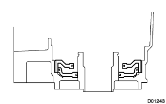
Coat new O-ring with ATF, and install it to the reaction sleeve.
-
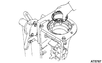
With the brake piston No.1 underneath (the rear side), install the brake reaction sleeve and the brake piston No.1 to the transmission case.
Note:Be careful not to damage the O-rings.
-
- Click here
INSTALL 1ST AND REVERSE BRAKE PISTON NO.2
-
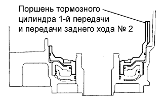
Coat new O-ring with ATF.
-
Install the O-ring on brake piston No.2.
-
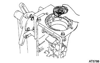
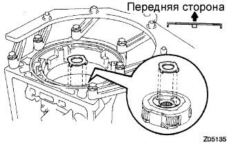
With the spring seat of the piston upwards (the front side), place the piston in the transmission case.
Note:Be careful not to damage the O-ring.
-
- Click here
INSTALL 1ST AND REVERSE BRAKE RETURN SPRING SUB-ASSEMBLY
-
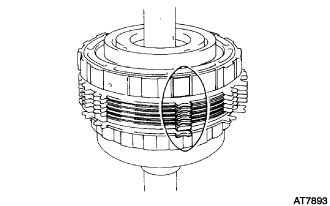
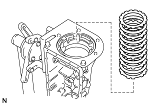
Place the piston return spring onto the 1st and reverse brake piston.
-
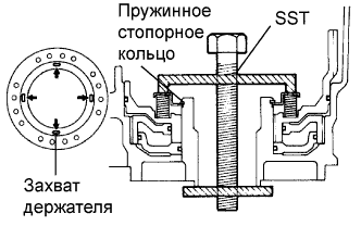
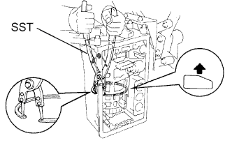
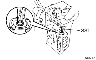
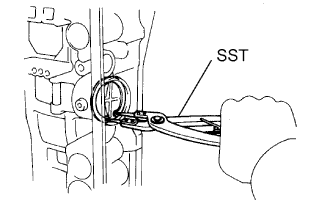
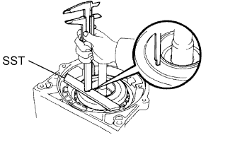
Set SST as shown, and compress the return spring with SST.
09350-30020 09350-07050 09350-07070 -
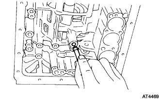
Using a screwdriver, install the snap ring. Make sure the end gap of the snap ring is not aligned with the spring retainer claw.
-
- Click here
INSPECT PISTON STROKE OF 1ST AND REVERSE BRAKE
- Click here
INSTALL REAR PLANETARY GEAR ASSEMBLY
-
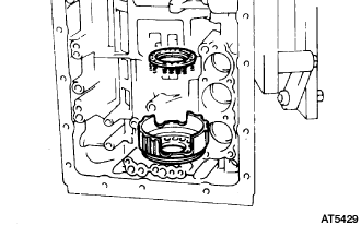
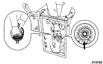
Install the leaf spring.
-
Install the flange with the rounded edge facing forward. Reinstall the plates and discs.
Install in order P = Plate D = Disc D - P - D - P - D - P - D - P - D - P - D - P -
Install the 2nd brake drum assembly.
-
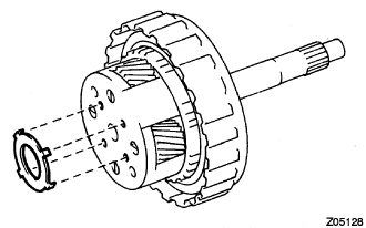
Coat the bearing with petroleum jelly and install it onto the case.
Table 1. Bearing diameter: Inside Outside 39.38 mm (1.5504 in.) 58.1 mm (2.2874 in.) -
Align the teeth on the flange, the discs and the plates.
-
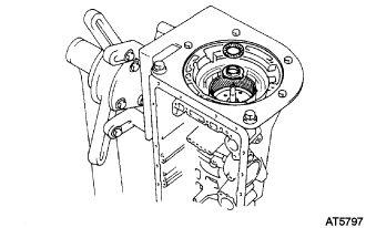
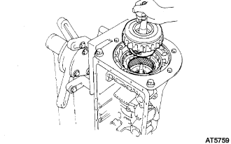
Align the splines of the transmission case with the assembled rear planetary gear, the 2nd brake drum, and the 1st and reverse brake pack with the output shaft,
-
Hold the output shaft with wooden blocks or equivalents.
-
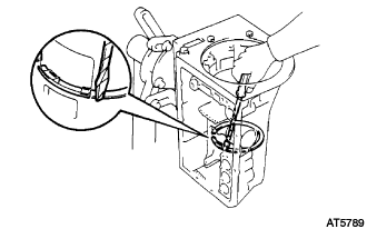
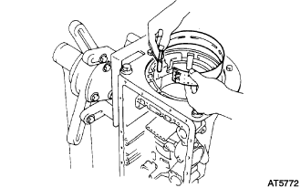
Using SST, install the snap ring.
09350-30020 09350-07060
-
- Click here
INSPECT PACK CLEARANCE OF FIRST AND REVERSE BRAKE
- Click here
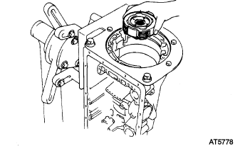
INSTALL 2ND BRAKE PISTON SLEEVE
-
Install the brake reaction sleeve.
-
- Click here
INSTALL BRAKE DRUM GASKET
-
Coat a new gasket with ATF.
-
Install the brake drum gasket.
-
- Click here
INSTALL 1 WAY CLUTCH ASSEMBLY
-
Install the thrust washer.
-
Install the 1 way clutch assembly.
-
- Click here
INSTALL 2ND BRAKE PACK
-
Install the 1.8 mm (0.071 in.) thick plate with the rounded edge side of the plate facing the disc.
-
Install the plates and discs.
Plate thickness 2.5 mm (0.098 in.) Install in order P = Plate D = Disc D - P - D - P - D - P - D - P - D - P -
Install the flange with the rounded edge of the flange facing the disc.
-
Using a screwdriver, install the snap ring.
-
- Click here
INSPECT PACK CLEARANCE OF SECOND BRAKE
- Click here
INSTALL PLANETARY SUN GEAR SUB-ASSEMBLY
-
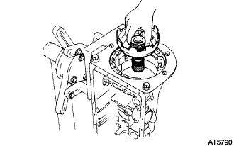
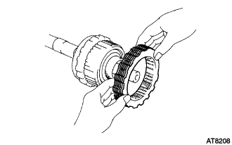
While turning the planetary sun gear clockwise, install it into the 1 way clutch.
Tip:Confirm the thrust washer is installed correctly.
-
- Click here
INSTALL FRONT PLANETARY GEAR ASSEMBLY
-
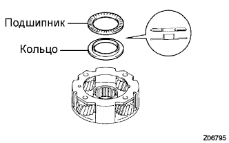
Coat the bearing and race with petroleum jelly and install them onto the front planetary gear.
Table 2. Bearing and race diameter: Inside Outside Bearing 35.5 mm (1.398 in.) 47.7 mm (1.878 in.) Race 33.7 mm (1.327 in.) 47.6 mm (1.874 in.) -
Install the front planetary gear to the sun gear input drum.
-
Using SST, install the snap ring.
09350-30020 09350-07070 -
Remove the wooden blocks or equivalent under the output shaft.
-
Coat the race with petroleum jelly, and install it onto the front planetary gear.
Table 3. Race diameter: Inside Outside 34.3 mm (1.350 in.) 47.8 mm (1.882 in.)
-
- Click here
INSTALL 2ND COAST BRAKE BAND ASSEMBLY
-
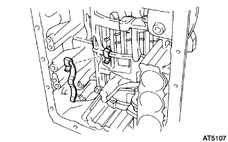
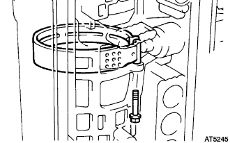
Install the 2nd coast brake band to the case.
-
Using needle-nose pliers, install the E-ring to the pin.
-
Install the pin through the brake band.
-
Using needle-nose pliers, install the E-ring to the pin.
-
- Click here
INSTALL DIRECT CLUTCH ASSEMBLY
-
Install the bearing and thrust washer to the forward clutch.
-
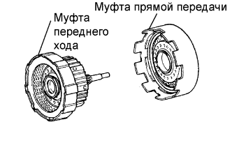
Install the direct clutch to the forward clutch.
-
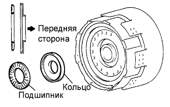
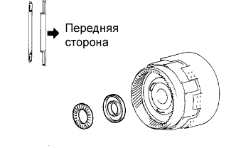
Coat the bearing and the race with petroleum jelly, and install them onto the forward clutch.
Table 4. Bearing and race diameter: Inside Outside Race 26.0 mm (1.024 in.) 48.9 mm (1.926 in.) Bearing 26.0 mm (1.024 in.) 46.7 mm (1.839 in.) -
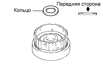
Coat the race with the petroleum jelly, and install it onto the front planetary ring gear.
Table 5. Race diameter: Inside Outside Race 26.8 mm (1.055 in.) 47.0 mm (1.850 in.) -
Align the flukes of the discs in the forward clutch.
-
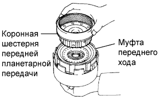
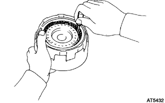
Align the splines of the front planetary ring gear with the flukes of the discs and install the front planetary ring gear to the forward clutch.
-
- Click here
INSTALL FRONT PLANETARY RING GEAR SUB-ASSEMBLY
-
Coat the bearing and the race with petroleum jelly, and install them onto the ring gear.
Table 6. Bearing and race diameter: Inside Outside Bearing 32.6 mm (1.283 in.) 47.7 mm (1.878 in.) Race 30.6 mm (1.205 in.) 53.6 mm (2.110 in.) -
Install the assembled direct clutch, the forward clutch and the front planetary ring gear into the transmission case.
-
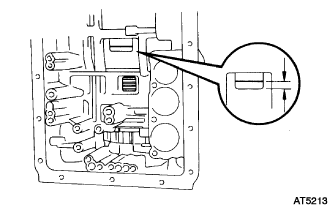
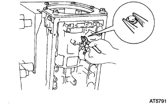
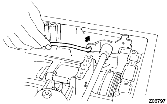
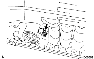
Using vernier calipers, measure the distance between the sun gear input drum and the direct clutch drum as shown in the illustration.
Height 5.3 to 7.3 mm (0.209 to 0.287 in.) If the distance is outside standard, check for an improper installation.
-
Coat the bearing with petroleum jelly and install it onto the forward clutch.
Table 7. Bearing diameter: Inside Outside Bearing 33.7 mm (1.327 in.) 47.6 mm (1.874 in.)
-
- Click here
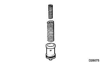
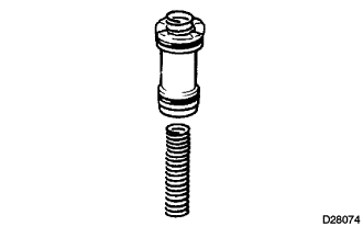
INSTALL 2ND COAST BRAKE PISTON
-
Coat 2 new O-rings with ATF and install them to the cover.
-
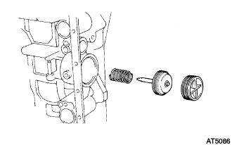
Install the spring, the piston assembly and the cover to the case.
-
Using SST, install the snap ring.
09350-30020 09350-07060
-
- Click here
INSPECT PISTON STROKE OF 2ND COAST BRAKE
- Click here
INSTALL OVERDRIVE SUPPORT SUB-ASSEMBLY
-
Coat the bearing and race with petroleum jelly, and install it onto the O/D support assembly.
Table 8. Bearing and race diameter: Inside Outside Bearing 36.8 mm (1.449 in.) 50.9 mm (2.004 in.) Race 36.8 mm (1.449 in.) 50.9 mm (2.004 in.) -
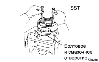
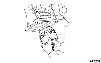
Using 2 bolts of SST, aim the bolt and the oil holes of the O/D support toward the valve body side, and align them with the bolt holes of the transmission case, and insert.
09350-30020 09350-07020 -
Temporarily tighten the 2 bolts.
-
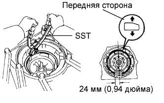
Using SST, install the snap ring.
09350-30020 09350-07060 Tip:Install the snap ring open end toward the valve body.
-
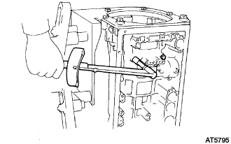
Torque the 2 bolts.
25 N*m 260 kgf*cm 19 ft.*lbf
-
- Click here
INSPECT OUTPUT SHAFT
- Click here
INSTALL OVERDRIVE BRAKE PACK
-
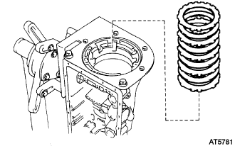
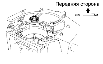
Install the 4.0 mm (0.157 in.) thick flange (flat ring) with the rounded edge side of the flange facing the discs.
-
Install the plates and discs.
Install in order P = Plate D = Disc P - D - P - D - P - D - P - D -
Install the flange (stepped ring) with the flat side of the flange facing the disc.
-
Using a screwdriver, install the snap ring.
-
- Click here
INSPECT OVERDRIVE BRAKE PISTON
- Click here
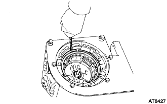
INSTALL OVERDRIVE PLANETARY GEAR ASSEMBLY
-
Coat the bearing and race with petroleum jelly, and install it onto the O/D support.
Table 9. Race diameter: Inside Outside Race 37.2 mm (1.465 in.) 58.8 mm (2.315 in.) -
Install the O/D planetary ring gear.
-
Coat the bearing and the race with petroleum jelly, and install them onto the planetary ring gear.
Table 10. Bearing and race diameter: Inside Outside Bearing 26.0 mm (1.024 in.) 46.8 mm (1.843 in.) Race 24.2 mm (0.953 in.) 47.8 mm (1.882 in.) -
Coat the race with petroleum jelly, and install it onto the planetary gear.
Table 11. Race diameter: Inside Outside 24.7 mm (0.9724 in.) 41.8 mm (1.646 in.) -
Install the O/D planetary gear, O/D direct clutch and one- way clutch.
-
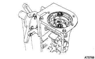
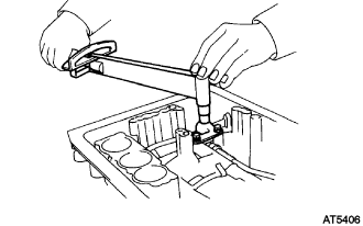
Place SST on the transmission case.
09350-36010 09350-06090 -
Using vernier calipers, measure distance between the tops of SST and the clutch drum.
Standard distance 15.5 to 16.5 mm (0.610 to 0.650 in.) If the distance is outside the standard, check for an improper installation.
-
Coat the bearing with petroleum jelly and install it onto the O/D direct clutch.
Table 12. Bearing and race diameter: Inside Outside Bearing 29.2 mm (1.150 in.) 50.2 mm (1.976 in.)
-
- Click here
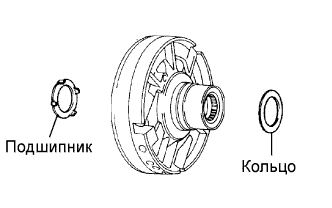
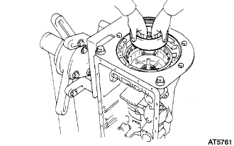
INSTALL OIL PUMP ASSEMBLY
-
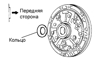
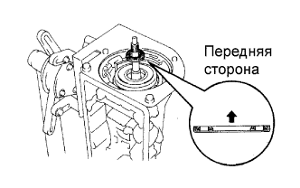
Coat the race with petroleum jelly, and install it onto the oil pump.
Table 13. Race diameter: Inside Outside Race 28.45 mm (1.120 in.) 47.3 mm (1.862 in.) -
Coat a new O-ring with ATF, and install it around the pump body.
-
Place the oil pump through the input shaft, and align the bolt holes of the pump body with the transmission case.
-
Hold the input shaft, and lightly press the oil pump body to slide the oil seal rings into the O/D direct clutch drum.
Note:Do not push on the oil pump strongly, or the oil seal ring will stick to the direct clutch drum.
-
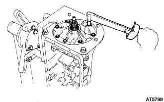
Install the 7 bolts.
22 N*m 220 kgf*cm 16 ft.*lbf
-
- Click here
INSPECT INPUT SHAFT SUB-ASSEMBLY
- Click here
INSPECT INDIVIDUAL PISTON OPERATION INSPECTION
- Click here
INSTALL MANUAL VALVE LEVER SHAFT OIL SEAL
-
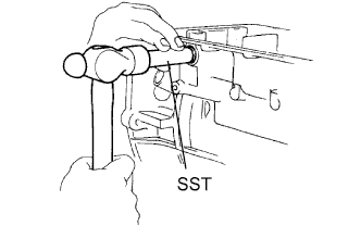
Using SST and a hammer, drive in 2 new manual valve lever shaft oil seals.
09350-30020 09350-07110
-
- Click here
INSTALL MANUAL VALVE LEVER SUB-ASSEMBLY
-
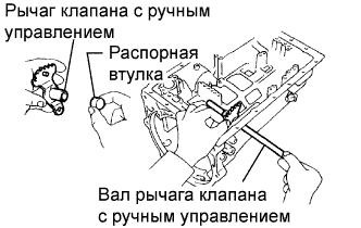
Install a new spacer to the manual valve lever.
-
Install the manual valve lever shaft to the transmission case through the manual valve lever.
-
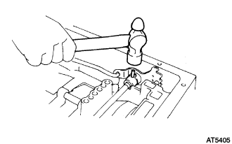
Using a hammer, drive in a new pin.
-
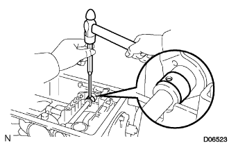
Align the manual valve lever indentation with the spacer hole and stake them with a punch.
-
Make sure the shaft rotates smoothly.
-
- Click here
INSTALL PARKING LOCK PAWL SHAFT
-
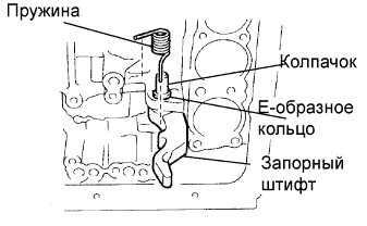
Install the E-ring to the shaft.
-
Install the parking lock pawl, the shaft and the spring.
-
- Click here
INSTALL PARKING LOCK ROD SUB-ASSEMBLY
-
Connect the parking lock rod to the manual valve lever.
-
- Click here
INSTALL PARKING LOCK PAWL BRACKET
-
Install the parking lock pawl bracket with the 3 bolts.
7.4 N*m 75 kgf*cm 65 in.*lbf -
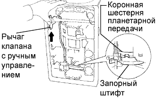
Shift the manual valve lever to the P position, and confirm that the planetary ring gear is correctly locked up by the lock pawl.
-
- Click here
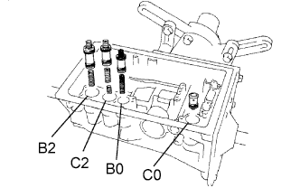
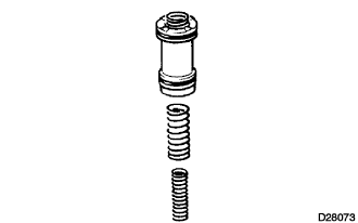
INSTALL C-0 ACCUMULATOR PISTON
-
Coat new O-ring with ATF, and install them to the piston.
-
Install the 2 springs and the accumulator piston to the hole.
Table 14. Accumulator spring: Spring Free length outer diameter mm (in.) Color C0 Inner 46.0 mm (1.811 in.)
14.02 mm (0.552 in.)
Yellow C0 Outer 74.6 mm (2.937 in.)
20.9 mm (0.823 in.)
Orange
-
- Click here
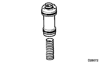
INSTALL B-0 ACCUMULATOR PISTON
-
Coat new O-rings with ATF, and install them to the piston.
-
Install the spring and the accumulator piston to the hole.
Table 15. Accumulator spring: Spring Free length outer diameter mm (in.) Color B0 62.0 mm (2.441 in.)
16.0 mm (0.630 in.)
Green
-
- Click here
INSTALL C-2 ACCUMULATOR PISTON
-
Coat new O-rings with ATF, and install them to the piston.
-
Install the 2 springs and the accumulator piston to the hole.
Table 16. Accumulator spring: Spring Free length outer diameter mm (in.) Color C2 Inner 42.1 mm (1.657 in.)
14.7 mm (0.579 in.)
Pink C2 Outer 68.53 mm (2.698 in.)
20.2 mm (0.795 in.)
Blue
-
- Click here
INSTALL B-2 ACCUMULATOR PISTON
-
Coat new O-rings with ATF, and install them to the piston.
-
Install the spring and the accumulator piston to the hole.
Table 17. Accumulator spring: Spring Free length outer diameter mm (in.) Color B2 70.5 mm (2.776 in.)
19.9 mm (0.783 in.)
Light green
-
- Click here
INSTALL CHECK BALL BODY
-
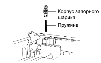
Install the check ball body and spring.
-
- Click here
INSTALL TRANSMISSION VALVE BODY ASSEMBLY
-
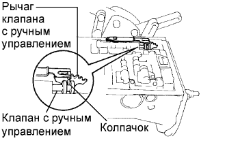
Align the groove of the manual valve with the pin of the lever.
-
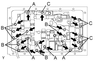
Install the 20 bolts.
11 N*m 112 kgf*cm 8 ft.*lbf Bolt length Bolt A 23 mm (0.91 in.) Bolt B 28 mm (1.10 in.) Bolt C 36 mm (1.42 in.)
-
- Click here
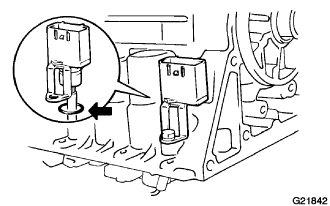
INSTALL TRANSMISSION WIRE
-
Coat a new O-ring with ATF, and install it to the transmission wire.
-
Install the solenoid wiring to the case, and then install the bolt.
5.4 N*m 55 kgf*cm 48 in.*lbf -
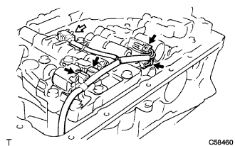
Connect the connectors to each shift solenoid valve.
-
- Click here
INSTALL VALVE BODY OIL STRAINER ASSEMBLY
-
Using a plastic hammer, install the pipe into the position.
Note:Be careful not to bend or damage the pipes.
-
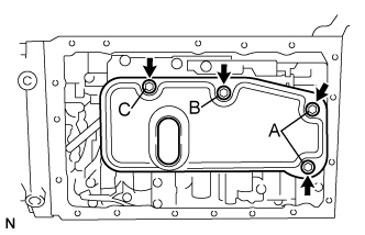
Install the oil strainer with the 4 bolts.
11 N*m 112 kgf*cm 8 ft.*lbf Bolt length Bolt A 16 mm (0.63 in.) Bolt B 20 mm (0.79 in.) Bolt C 28 mm (1.10 in.)
-
- Click here
INSTALL TRANSMISSION OIL CLEANER MAGNET
-
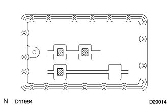
Install the 3 magnets on the oil pan.
-
- Click here
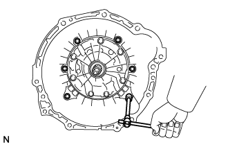
INSTALL AUTOMATIC TRANSMISSION OIL PAN SUB-ASSEMBLY
-
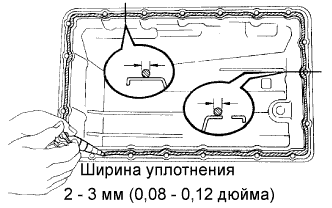
Remove any FIPG material and be careful not to drop oil on the contacting surfaces of the transmission case and the oil pan.
-
Apply FIPG to the oil pan.
FIPG Toyota Genuine Seal Packing 1281, Three Bond 1281 or equivalent -
Install the oil pan with the 19 bolts.
7.4 N*m 75 kgf*cm 65 in.*lbf
-
- Click here
INSTALL SENSOR ROTOR
-
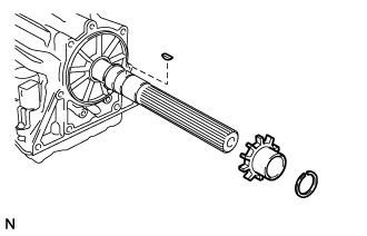
Using a snap ring expander, install the front side snap ring.
-
Install the key and sensor rotor.
-
Using a snap ring expander, install the rear side snap ring.
-
- Click here
INSTALL EXTENSION HOUSING DUST DEFLECTOR
-
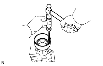
Using a screwdriver and hammer, install new extension housing dust deflector.
-
- Click here
INSTALL AUTOMATIC TRANSMISSION EXTENSION HOUSING OIL SEAL
-
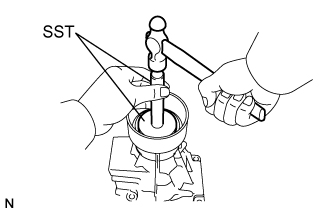
Using SST and a hammer, install a new extension housing oil seal.
09950-60020 09951-00580 09950-70010 09951-07100 Oil seal in depth 5.8 to 6.2 mm (0.228 to 0.244 in.)
-
- Click here
INSTALL EXTENSION HOUSING BUSH APPLY TUBE
-
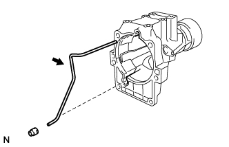
Install the extension housing bush apply tube.
-
- Click here
INSTALL EXTENSION HOUSING BUSH APPLY TUBE GASKET
-
Install the extension housing bush apply tube gasket.
-
- Click here
INSTALL EXTENSION HOUSING SUB-ASSEMBLY
-
Apply seal packing or equivalent to the 6 bolts.
Seal packing Toyota Genuine Adhesive 1344, Three Bond 1344 or equivalent -
Install the extension housing and a new gasket to the case with the 6 bolts.
36 N*m 370 kgf*cm 27 ft.*lbf Tip:The 2 lower bolts are shorter.
-
- Click here
INSTALL TRANSMISSION REVOLUTION SENSOR
-
Coat a new O-ring with ATF, and install it to the sensor.
-
Install the revolution sensor with the bolt.
5.4 N*m 55 kgf*cm 48 in.*lbf
-
- Click here
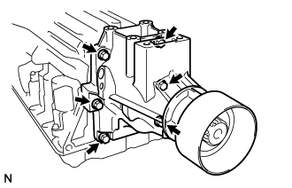
INSTALL AUTOMATIC TRANSMISSION HOUSING
-
Install the transmission housing with the 6 bolts.
Torque 14 mm bolt 34 N*m (345 kgf*cm, 25 ft.*lbf) 17 mm bolt 57 N*m (580 kgf*cm, 42 ft.*lbf)
-
- Click here
INSTALL SPEED SENSOR
-
Coat a new O-ring with ATF, and install it to the sensor.
-
Install the speed sensor.
5.4 N*m 55 kgf*cm 48 in.*lbf
-
- Click here
INSTALL TEMPERATURE SENSOR
-
Coat a new O-ring with ATF, and install it to the temperature sensor.
-
Install the temperature sensor.
15 N*m 160 kgf*cm 11 ft.*lbf
-
- Click here
INSTALL OIL COOLER TUBE UNION
-
Coat a new O-rings with ATF, and install them to the unions.
-
Install the oil cooler tube unions.
29 N*m 300 kgf*cm 22 ft.*lbf
-
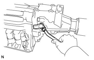
- Click here
INSTALL PARK/NEUTRAL POSITION SWITCH ASSEMBLY
-
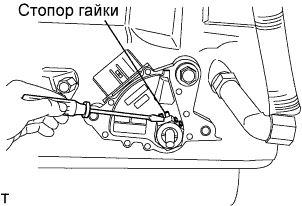
Install the park/neutral position switch onto the manual valve lever shaft, and temporarily tighten the adjusting bolt.
-
Install the nut stopper and a new lock washer. Install the nut.
6.9 N*m 70 kgf*cm 61 in.*lbf -
Using the control shaft lever, fully turn the manual lever shaft back, and then return 2 notches. It is now in neutral.
-
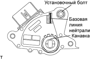
Align the neutral basic line with the switch groove, and tighten the adjusting bolt.
13 N*m 130 kgf*cm 9 ft.*lbf -
Bend the tabs of the lock washer.
Tip:Bend at least 2 of the lock washer tabs.
-
- Click here
INSTALL TRANSMISSION CASE PLUG ASSEMBLY
-
Coat a new O-ring with ATF, and install it to the plug.
-
Install the cable to the case with the bolt.
5.4 N*m 55 kgf*cm 48 in.*lbf
-
- Click here
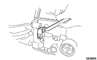
INSTALL TRANSMISSION CONTROL SHAFT LEVER LH
-
Install the transmission control shaft lever and the washer. Install the nut.
16 N*m 160 kgf*cm 12 ft.*lbf
-
- Click here
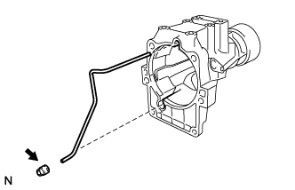
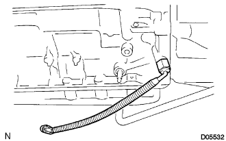
INSTALL BREATHER PLUG HOSE
-
Install the breather plug hose.
-
- Click here
INSTALL DRAIN (ATM) PLUG SUB-ASSEMBLY
20 N*m 205 kgf*cm 15 ft.*lbf