-
Use the same procedure for RHD vehicles and LHD vehicles.
-
The procedure listed below is for LHD vehicles.
- Click here
REMOVE SHIFT LEVER CAP
-
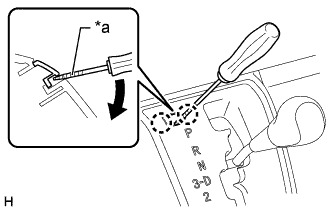
Using a screwdriver, detach the 2 claws and remove the shift lever cap from the floor shift position indicator housing sub-assembly.
Table 1. Text in Illustration *a Protective Tape Note:Be careful not to damage the shift lever cap and floor shift position indicator housing sub-assembly.
Tip:Tape the screwdriver tip before use.
-
- Click here
REMOVE SHIFT LEVER KNOB
-
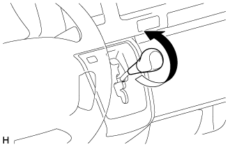
Twist the shift lever knob in the direction indicated by the arrow and remove it.
-
- Click here
REMOVE FLOOR SHIFT POSITION INDICATOR HOUSING SUB-ASSEMBLY
-
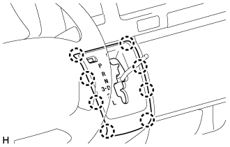
Detach the 8 claws and remove the floor shift position indicator housing sub-assembly.
-
- Click here
REMOVE INSTRUMENT PANEL UNDER COVER SUB-ASSEMBLY NO. 1
-
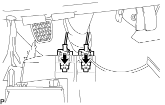
С помощью съемника фиксаторов освободите 2 фиксатора.
-
Освободите 3 захвата и снимите нижнюю крышку панели приборов № 1.
-
- Click here
REMOVE INSTRUMENT PANEL FINISH PANEL LOWER
-
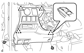
С помощью съемника фиксаторов освободите 2 фиксатора.
-
Освободите 4 захвата и снимите нижнюю отделочную накладку панели приборов.
-
Отсоедините все разъемы.
-
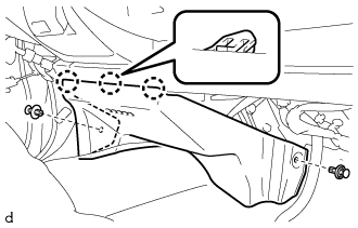
Нажмите на точки, указанные на рисунке стрелками, чтобы отсоединить трос блокировки топливной крышки и трос управления замком капота от нижней отделочной накладки панели приборов.
-
- Click here
REMOVE PARKING BRAKE HOLE COVER
-
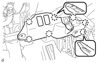
Освободите 6 захватов и снимите крышку отверстия стояночного тормоза.
-
Отсоедините все разъемы.
-
- Click here
REMOVE INSTRUMENT PANEL FINISH PANEL LOWER CENTER
-
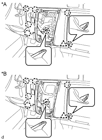
Освободите 8 захватов и снимите нижнюю центральную отделочную накладку панели приборов.
Table 2. Обозначения на рисунке *A для моделей с механической трансмиссией *B для моделей с автоматической трансмиссией
-
- Click here
DISCONNECT TRANSMISSION CONTROL CABLE ASSEMBLY
-
Move the shift lever to N.
-
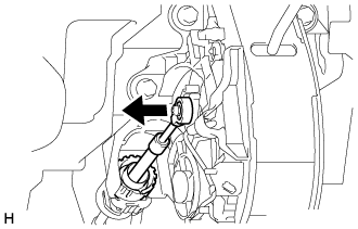
Disconnect the end of the transmission control cable assembly from the shift lock control unit assembly.
-
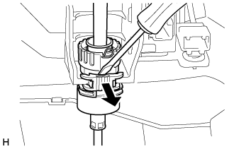
Using a screwdriver, pull out the stopper of the transmission control cable assembly.
Tip:Do not remove the stopper. If the stopper is removed, reinstall it to its original position.
-
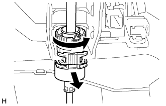
Rotate the nut counterclockwise approximately 180° and, while holding the nut in that position, disconnect the transmission control cable from the shift lock control unit assembly.
Note:Do not over-rotate the nut as it will come off the internal spring and the transmission control cable will not be reusable.
-
- Click here
REMOVE SHIFT LOCK CONTROL UNIT ASSEMBLY
-
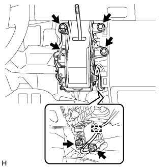
Disconnect the 2 connectors and clamp from the shift lock control unit assembly.
-
Remove the 4 bolts and shift lock control unit assembly.
-