| DTC Code | DTC Name |
|---|---|
| P0751/62 | Shift Solenoid "A" Malfunction (Shift Solenoid Valve S1) |
DESCRIPTION
The TCM uses signals from the vehicle speed sensor and direct clutch speed sensor to detect the actual gear position (1st, 2nd, 3rd or 4th gear).
Then the TCM compares the actual gear with the shift schedule in the TCM memory to detect mechanical problems of the shift solenoid valves, valve body or automatic transmission (clutch, brake or gear etc.).
| DTC No. | DTC Detection Condition | Trouble Area |
|---|---|---|
| P0751/62 | The gear required by the TCM does not match the actual gear when driving. (2-trip detection logic) |
|
MONITOR DESCRIPTION
This DTC indicates "stuck ON malfunction" or "stuck OFF malfunction" of the shift solenoid valve S1.
The TCM commands gear shifts by turning the shift solenoid valves "ON/OFF". When the gear position commanded by the TCM and the actual gear position are not the same, the TCM illuminates the MIL and stores the DTC.
INSPECTION PROCEDURE
PROCEDURE
- Click here
CHECK OTHER DTCS OUTPUT (IN ADDITION TO DTC P0751/62)
-
Connect the intelligent tester to the DLC3.
-
Turn the ignition switch to the ON position.
-
Turn on the tester.
-
Select the item "Powertrain / ECT / DTC / Current or Pending".
-
Read the DTCs using the intelligent tester.
Result Display (DTC output) Proceed to Only "P0751/62" is output A "P0751/62" and other DTCs B Tip:
-
If any other codes besides "P0751/62" are output, perform troubleshooting for those DTCs first.
-
When not using the intelligent tester, refer to DTC CHECK / CLEAR (Click here).
-
-
- Click here
INSPECT SHIFT SOLENOID VALVE S1
-
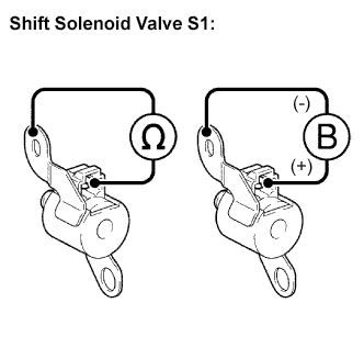
Remove the shift solenoid valve S1.
-
Measure the resistance.
Standard resistance Tester Connection Specified Condition
20°C (68°F)
Solenoid Connector (S1) - Solenoid Body (S1) 11 to 15 Ω -
Connect the positive (+) lead to the terminal of the solenoid connector, and the negative (-) lead to the solenoid body.
OK The solenoid makes an operating sound.
- OKClick here
- NGClick here
-
- Click here
INSPECT TRANSMISSION VALVE BODY ASSEMBLY
OK There are no foreign objects on each valve.
- OKClick here
- NGClick here
- Click here
REPAIR OR REPLACE AUTOMATIC TRANSMISSION ASSEMBLY
- Click here
GO TO DTC CHART
- Click here
REPLACE SHIFT SOLENOID VALVE S1
- Click here
REPAIR OR REPLACE TRANSMISSION VALVE BODY ASSEMBLY