Click here
-
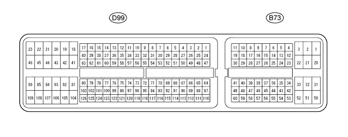
ECM (for 1KD-FTV w/ DPF)
Tip:Each ECM terminal's standard voltage is shown in the table below.
In the table, first follow the information under "Condition". Look under "Symbols (Terminal No.)" for the terminals to be inspected. The standard voltage between the terminals is shown under "Specific Condition".
Use the illustration above as a reference for the ECM terminals.
Symbols (Terminals No.) Wiring Color Terminal Description Condition Specified Condition NSW (D99-38) - E1 (D99-109) B - W-B Park neutral switch signal Ignition switch ON and shift lever P and N position Below 2 V Ignition switch ON and shift lever except P and N position 11 to 14 V STP (B73-35) - E1 (D99-109) Y - W-B Stop light switch signal Brake pedal is depressed 7.5 to 14 V Brake pedal is released Below 1.5 V CAN+ (D99-40) - E1 (D99-109) L - W-B CAN communication line Ignition switch ON Pulse generation
(See waveform 5)
CAN- (D99-63) - E1 (D99-109) Y - W-B CAN communication line Ignition switch ON Pulse generation
(See waveform 6)
TC (B73-26) - E1 (D99-109) G - W-B Terminal TC of DLC3 Ignition switch ON 11 to 14 V -

ECM (for 1KD-FTV w/o DPF)
Tip:Each ECM terminal's standard voltage is shown in the table below.
In the table, first follow the information under "Condition". Look under "Symbols (Terminal No.)" for the terminals to be inspected. The standard voltage between the terminals is shown under "Specific Condition".
Use the illustration above as a reference for the ECM terminals.
Symbols (Terminals No.) Wiring Color Terminal Description Condition Specified Condition NSW (D98-38) - E1 (D98-109) B - W-B Park neutral switch signal Ignition switch ON and shift lever P and N position Below 2 V Ignition switch ON and shift lever except P and N position 11 to 14 V STP (B72-35) - E1 (D98-109) Y - W-B Stop light switch signal Brake pedal is depressed 7.5 to 14 V Brake pedal is released Below 1.5 V CAN+ (D98-40) - E1 (D98-109) L - W-B CAN communication line Ignition switch ON Pulse generation
(See waveform 5)
CAN- (D98-63) - E1 (D98-109) Y - W-B CAN communication line Ignition switch ON Pulse generation
(See waveform 6)
TC (B72-26) - E1 (D98-109) G - W-B Terminal TC of DLC3 Ignition switch ON 11 to 14 V -
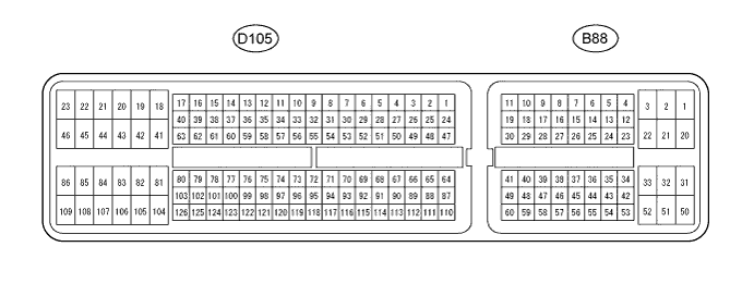
ECM (for 2KD-FTV)
Tip:Each ECM terminal's standard voltage is shown in the table below.
In the table, first follow the information under "Condition". Look under "Symbols (Terminal No.)" for the terminals to be inspected. The standard voltage between the terminals is shown under "Specific Condition".
Use the illustration above as a reference for the ECM terminals.
Symbols (Terminals No.) Wiring Color Terminal Description Condition Specified Condition NSW (D105-38) - E1 (D105-109) B - BR Park neutral switch signal Ignition switch ON and shift lever P and N position Below 2 V Ignition switch ON and shift lever except P and N position 11 to 14 V STP (B88-35) - E1 (D105-109) Y - BR Stop light switch signal Brake pedal is depressed 7.5 to 14 V Brake pedal is released Below 1.5 V CAN+ (B88-4) - E1 (D105-109) L - BR CAN communication line Ignition switch ON Pulse generation
(See waveform 5)
CAN- (B88-5) - E1 (D105-109) Y - BR CAN communication line Ignition switch ON Pulse generation
(See waveform 6)
TC (B88-26) - E1 (D105-109) G - BR Terminal TC of DLC3 Ignition switch ON 11 to 14 V -
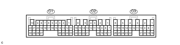
TCM
Tip:Each TCM terminal's standard voltage is shown in the table below.
In the table, first follow the information under "Condition". Look under "Symbols (Terminal No.)" for the terminals to be inspected. The standard voltage between the terminals is shown under "Specific Condition".
Use the illustration above as a reference for the TCM terminals.
Symbols (Terminals No.) Wiring Color Terminal Description Condition Specified Condition P (O1-13) - E1 (O1-1) W - W-B P shift position switch signal Ignition switch ON and shift lever P position 11 to 14 V Ignition switch ON and shift lever except P position Below 1 V N (O1-14) - E1 (O1-1) GR - W-B N shift position switch signal Ignition switch ON and shift lever N position 11 to 14 V Ignition switch ON and shift lever except N position Below 1 V D (O2-8) - E1 (O1-1) W - W-B D shift position switch signal Ignition switch ON and shift lever D or 3 position 11 to 14 V Ignition switch ON and shift lever except D or 3 position Below 1 V L (O2-10) - E1 (O1-1) R - W-B L shift position switch signal Ignition switch ON and shift lever L position 11 to 14 V Ignition switch ON and shift lever except L position Below 1 V 2 (O2-11) - E1 (O1-1) Y - W-B 2 shift position switch signal Ignition switch ON and shift lever 2 position 11 to 14 V Ignition switch ON and shift lever except 2 position Below 1 V R (O2-9) - E1 (O1-1) L - W-B R shift position switch signal Ignition switch ON and shift lever R position 11 to 14 V Ignition switch ON and shift lever except R position Below 1 V 3 (O2-12) - E1 (O1-1) B - W-B 3 shift position switch signal Ignition switch ON and shift lever 3 position 11 to 14 V Ignition switch ON and shift lever except 3 position Below 1 V STP (O3-14) - E1 (O1-1) Y - W-B Stop light switch signal Brake pedal is depressed 7.5 to 14 V Brake pedal is released Below 1.5 V S2 (O1-17) - E1 (O1-1) P - W-B S2 solenoid signal 2nd or 3rd gear 11 to 14 V 1st or 4th gear Below 1 V S1 (O1-18) - E1 (O1-1) LG - W-B S1 solenoid signal 1st or 2nd gear 11 to 14 V 3rd or 4th gear Below 1 V SLT+ (O1-20) - SLT- (O1-19) V - W SLT solenoid signal Engine idling Pulse generation
(See waveform 1)
SLU+ (O1-21) - SLU- (O1-22) B - L SLU solenoid signal*1 Engine idling Pulse generation
(See waveform 7)
SL (O1-16) - E1 (O1-1) GR - W-B SL solenoid signal*2 Ignition switch ON Below 1.5 V Vehicle driving under lock-up position 11 to 14 V THOC (O1-24) - E2 (O1-23) L - Y ATF temperature sensor signal ATF temperature: 115°C (239°F) or more Below 1.5 V THO (O1-25) - E2 (O1-23) GR - Y No. 1 ATF temperature sensor signal*1 ATF temperature: 115°C (239°F) or more Below 1.5 V SP2+ (O1-30) - SP2- (O1-29) R - G Speed sensor (SP2) signal Vehicle speed 20 km/h (12 mph) Pulse generation
(See waveform 3)
NC0+ (O1-3) - NC0- (O1-2) L - Y Speed sensor (NC0) signal Engine idling (P or N position) Pulse generation
(See waveform 2)
NSW (O1-12) - E1 (O1-1) B - W-B Park neutral switch signal Ignition switch ON and shift lever P and N position Below 2 V Ignition switch ON and shift lever except P and N position 11 to 14 V STA (O1-11) - E1 (O1-1) R - W-B Starter signal Cranking (shift lever position P or N position, engine Start) 6 V or more Ignition switch ON and shift lever except P and N position 11 to 14 V SPD1 (O3-25) - E1 (O1-1) P - W-B Speed signal from combination meter Vehicle speed 20 km/h (12 mph) Pulse generation
(See waveform 4)
BATT (O3-5) - E1 (O1-1) B - W-B Battery (for measuring battery voltage and for TCM memory) Always 11 to 14 V IG2 (O3-6) - E1 (O1-1) B - W-B Ignition switch Ignition switch ON 11 to 14 V CAN+ (O3-21) - E1 (O1-1) L - W-B CAN communication line Engine is stopped, ignition switch ON Pulse generation
(See waveform 5)
CAN- (O3-20) - E1 (O1-1) Y - W-B CAN communication line Engine is stopped, ignition switch ON Pulse generation
(See waveform 6)
*1: w/ Flex Lock Up
*2: w/o Flex Lock Up
-
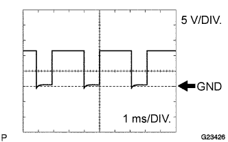
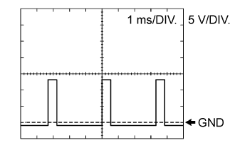
Waveform 1
Table 1. Reference: Terminal SLT+ - SLT- Tool setting 5 V/DIV., 1ms/DIV. Vehicle condition Engine idling -
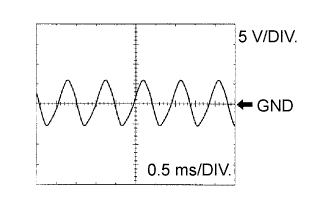
Waveform 2
Table 2. Reference: Terminal NC0+ - NC0- Tool setting 5 V/DIV., 0.5 ms/DIV. Vehicle condition Engine idling (P or N position) -
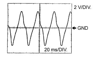
Waveform 3
Table 3. Reference: Terminal SP2+ - SP2- Tool setting 2 V/DIV., 20 ms/DIV. Vehicle condition Vehicle speed 20 km/h (12 mph) -
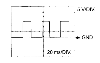
Waveform 4
Table 4. Reference: Terminal SPD1 - E1 Tool setting 5 V/DIV., 20 ms/DIV. Vehicle condition Vehicle speed 20 km/h (12 mph) -
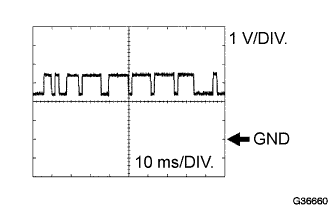
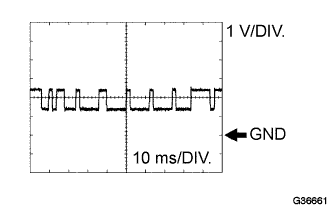
Waveform 5
Table 5. Reference: Terminal CAN+ - E1 Tool setting 1 V/DIV., 10 ms/DIV. Vehicle condition Engine is stopped, ignition switch ON -
Waveform 6
Table 6. Reference: Terminal CAN- - E1 Tool setting 1 V/DIV., 10 ms/DIV. Vehicle condition Engine is stopped, ignition switch ON -
Waveform 7
Table 7. Reference: Terminal SLU+ - SLU- Tool setting 5 V/DIV., 1 ms/DIV. Vehicle condition Engine idling (P or N position)
-